
Lancet device and method

a technology of lancets and needles, which is applied in the field of lancets, can solve the problems of unnecessary pain and discomfort for users, frequent drawing of blood, and high pain resulting from its use, and achieves the effects of convenient use and loading, reduced pain, and easy control or adjustmen

Inactive Publication Date: 2009-01-29
VIROTEK LLC
View PDF11 Cites 74 Cited by
  • Summary
  • Abstract
  • Description
  • Claims
  • Application Information

AI Technical Summary

Benefits of technology

"The present invention is an improvement on existing lancets. It is easy to use, loads with existing lancets on the market, and is quieter in use. The lancet tip moves quickly and without vibration or oscillation, resulting in a quick and straight piercing in the user, reducing pain associated with the lancing process. The piercing depth can also be easily controlled or adjusted. The device can be customized to a particular user's desires and repeated over and over, ensuring each piercing is substantially the same."

Problems solved by technology

However, for many, drawing blood can be frequent.
Such devices cover a spectrum from simple, e.g., a finger pricking device (needle, pin, lancet), to quite complicated (mechanical or electronic devices).
Central to any device is the amount of pain resulting from its use.
Side-to-side vibration (transverse oscillation) of a lancet's tip while moving to puncture skin causes an irregular puncture, causing unnecessary pain and discomfort to a user.
Finally, speed of the lancing device into and out of the lancing site affects pain greatly.

Method used


Image

  • Lancet device and method
  • Lancet device and method
  • Lancet device and method

Examples


Embodiment Construction

[0020]While this invention is susceptible of embodiments in many different forms, there is shown in the drawings and will herein be described in detail, preferred embodiments of the invention with the understanding the present disclosure is to be considered as an exemplification of the principles of the invention and is not intended to limit the broad aspect of the invention to the embodiments illustrated.

[0021]The present invention uses the full, complete, 360 degrees, magnetic field of a magnet to project the tip of a lancet outwardly from the device from a safe, steady state position to a puncturing position and to retract the lancet back into the protected, steady state position. The complete use of the magnetic field reduces oscillation, or movement, of the tip in directions other than the traveling direction of the tip. This greatly increases the efficiency of the lancet and reduces pain potentially caused thereby.

The Components of the Lancing Device 10

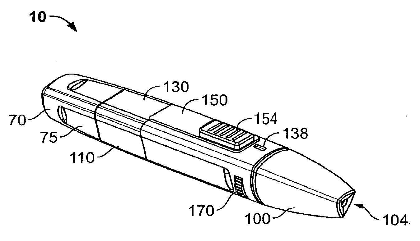
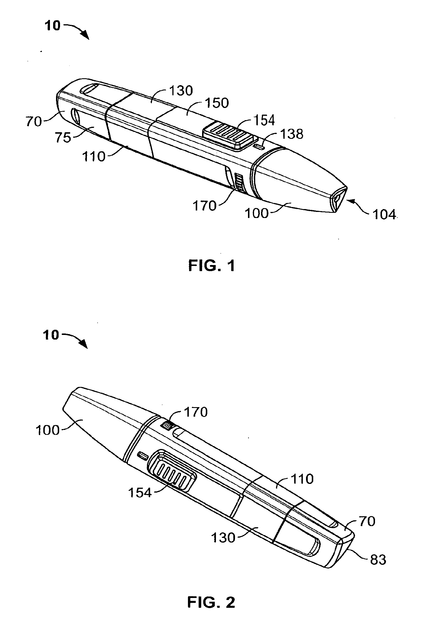
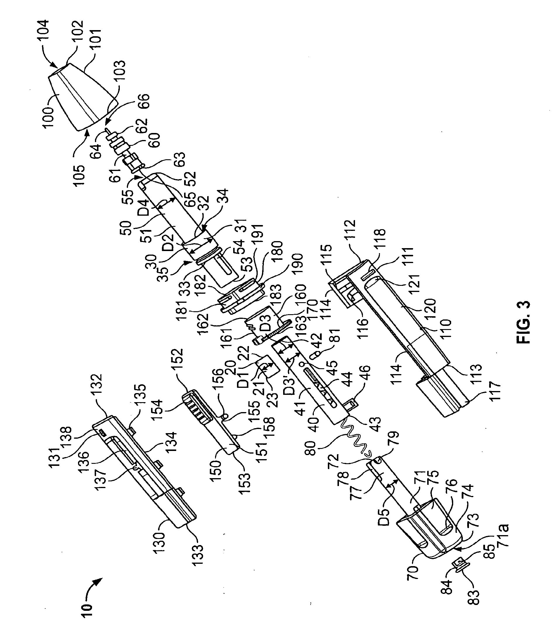
[0022]FIG. 1 is an explo...


PUM


Abstract

A lancet device (10) having an internal magnet (20) and the forces emanating therefrom driving and retracting a collar (30) and a lancet (60). The device has a steady state condition (SS) wherein the device is at rest and in equilibrium. The device can be armed and activated to puncture. Once puncturing has occurred the device returns to a steady state condition.A lancet method involves positioning both a magnet (20) and a member (30) capable of being affected thereby with a lancet (60) in communications with one of either the magnet or the member, positioning either the member (30) or the magnet (20) to an armed position wherein the magnetic forces from the magnetic affect the member, and releasing the one of either the member or the magnet from the armed position permitting movement between the member and magnet by at least, in part, the magnetic forces, resulting in the movement of the lancet from a withdrawn position to the piercing position.

Description

TECHNICAL FIELD[0001]The present invention generally relates to lancets, and more particularly, to a magnetically driven lancet.BACKGROUND OF THE INVENTION[0002]In treating several medical conditions or injuries, samples of blood must be taken and tested. For example, to treat diabetes with insulin, blood sugar levels must be checked, or monitored, regularly. As a result, blood must be drawn from the individual requiring the check and tested by any one of a number of known methods. One such method is placing a small amount of blood on a test strip and having the test strip read in a specially designed meter.[0003]Many advances have reduced the amount or volume of blood needed for medical tests. However, for many, drawing blood can be frequent. In addition, for many medical conditions or injuries, individuals draw their own blood without the need of professional medical personnel. The result of this has been the development of personal lancing devices for individuals to draw their ow...

Claims


Application Information

Patent Timeline
Patent Type & Authority Applications(United States)
IPC IPC(8): A61B17/32A61B5/15
CPCA61B5/15186A61B5/1411A61B5/150022A61B5/150183A61B5/150259A61B5/15029A61B5/150412A61B5/150503A61B5/15113A61B5/15123A61B5/1513A61B5/1519A61B5/15194
Inventor KUDRNA, PAULSCHWARTZ, BRIANSCHWARTZ, MARK
Owner VIROTEK LLC
Learn More