Unlock instant, AI-driven research and patent intelligence for your innovation.
External combustion engine
Inactive Publication Date: 2009-02-05
DENSO CORP
View PDF10 Cites 0 Cited by
Summary
Abstract
Description
Claims
Application Information
AI Technical Summary
This helps you quickly interpret patents by identifying the three key elements:
Problems solved by technology
Method used
Benefits of technology
Benefits of technology
[0015]In view of the points described above, the object of this invention is to provide an external combustion engine capable of producing a predetermined output quickly after engine start.
Problems solved by technology
As long as the vapor of the working fluid is accumulated in the main container when the external combustion engine stops; however, the saturated vapor pressure of the working fluid also drops with the heater temperature, resulting in condensation and liquefaction of the vapor of the working fluid.
Once the internal pressure of the main container drops below the internal pressure of the auxiliary container, the working fluid in the auxiliary container gradually begins to flow into the main container through the choke, and the volume of the working fluid in the main container increases excessively.
Since only a small amount of the working fluid can flow through the choke at a time, considerable time is required before all of the excess working fluid in the main container returns to the auxiliary container.
As a result, a predetermined output cannot be produced, before all of the excess working fluid in the main container can return to the auxiliary container after the engine restarts, thereby posing the problem that the restarting time is lengthened before the predetermined output is obtained.
In order to avoid the above engine restart problem, the external combustion engine is required to be stopped at a when the vapor of the working fluid is not accumulated in the main container, thereby greatly complicating the operation to stop the external combustion engine.
Method used
Image
Click on the blue label to locate the original text in one second.
Reading with bidirectional positioning of images and text.
Examples
first embodiment
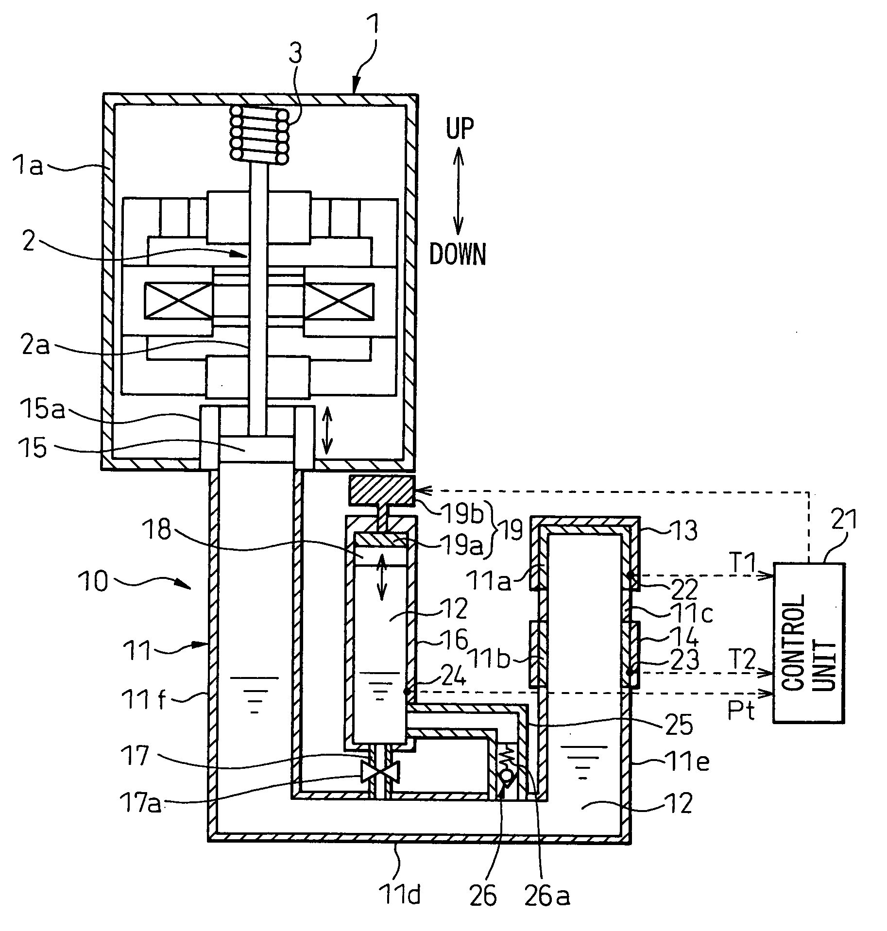
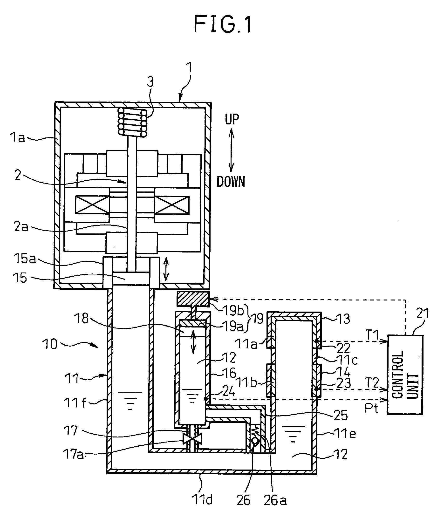
[0055]A first embodiment is explained below with reference to FIGS. 1 to 7. In this embodiment, the external combustion engine 10 according to the invention is used for a power generating system. FIG. 1 is a diagram showing a general configuration of the power generating system according to this embodiment. The basic configuration of this power generating system is similar to that of the prior application described above, and therefore, the configuration in common with the prior application is explained below first.
[0056]The external combustion engine 10 according to this embodiment drives a power generator 1 for generating the electromotive force by vibratory displacement of a movable member 2 with a permanent magnet buried therein, and includes a main container 11 sealed with a working fluid 12 adapted to flow in liquid state, a heater 13 for heating and gasifying the working fluid 12 in the main container 11 and a cooler 14 for cooling the vapor of the working fluid 12 heated and...
second embodiment
[0127]In the second embodiment, unlike in the first embodiment, a valve 30 for opening / closing the second connection pipe 25 is added as shown in FIG. 8. The operation of the valve 30 is controlled by the control unit 21. The valve 30 and the control unit 21, together with the first connection pipe 17, the choke 17a, the second connection pipe 25 and the check valve 26, makes up the communication area adjusting means.
[0128]The valve 30 is controlled by the control unit 21 to be closed in normal operation mode and open only at the time of starting the external combustion engine 10. Even in the case where the check valve 26 is open in the normal operation mode of the external combustion engine 10, therefore, the working fluid 12 is prevented by the valve 30 from flowing into the auxiliary container 16 through the second connection pipe 25.
[0129]As a result, unlike in the first embodiment, the operating pressure ΔP of the check valve 26 is not required to be set to a value larger than ...
third embodiment
[0133]According to the third embodiment, unlike in the first embodiment, the operating pressure ΔP of the check valve 26 can be controlled variably as shown in FIG. 9.
[0134]Specifically, the spring portion 26a of the check valve 26 is formed of a shape memory alloy or bimetal so that the spring constant of the spring portion 26a changes with temperature. Further, the operating pressure ΔP of the check valve 26 changes in accordance with the change in the spring constant of the spring portion 26a. Alternatively, the spring portion 26a may not have such a characteristic as to change the spring constant thereof with temperature, but a thermostat adapted to expand / contract with temperature may be provided to change the operating pressure ΔP of the check valve 26.
[0135]The spring portion 26a is heated by the heater 31 which in turn is controlled by the control unit 21.
[0136]According to this embodiment, the heater 31 is configured of an actuator for energizing the spring portion 26a, whi...
PUM
Abstract
An external combustion engine includes: a main container sealed with a working fluid in a liquid state adapted to flow; a heater for heating a portion of the working fluid in the main container and generating the vapor of the working fluid; a cooler for cooling and liquefying the vapor; an output unit for outputting by converting the displacement of the liquid portion of the working fluid generated by the volume change of the working fluid due to the generation and liquefaction of the vapor into mechanical energy; and an auxiliary container communicating with the main container. The heater, the cooler and the output unit are arranged in order, in the direction of displacement of the working fluid. The working fluid is sealed in the auxiliary container which communicates with the portion of the main container nearer the output unit than the cooler. The engine further includes a communication area adjusting unit for establishing communication between the main container and the auxiliary container with a first communication area in normal operation mode and with a second communication area larger than the first communication area at the time of engine start. Thus, a predetermined output is produced quickly after engine start.
Description
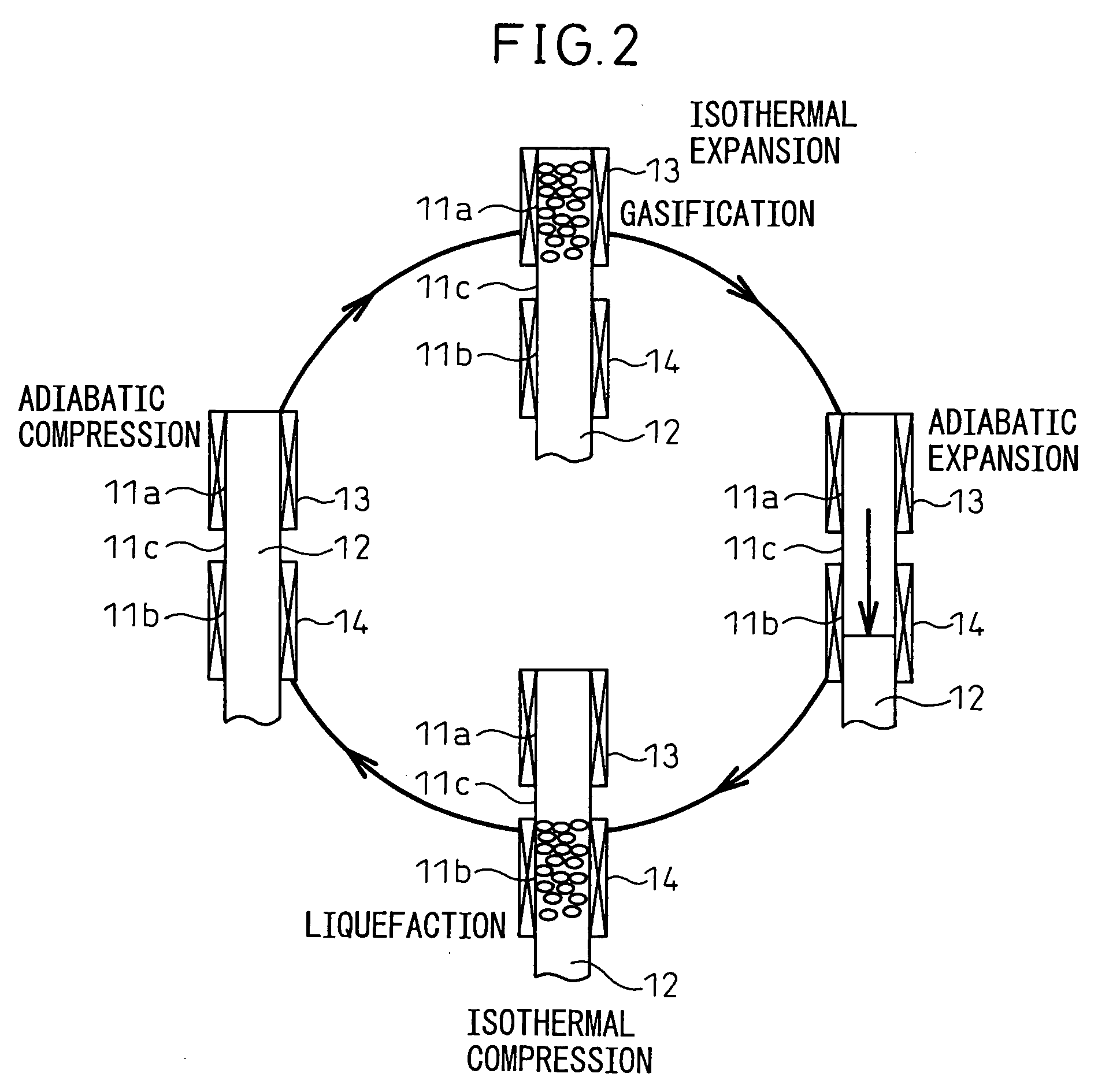
BACKGROUND OF THE INVENTION[0001]1. Field of the Invention[0002]This invention relates to an external combustion engine for converting the displacement of a liquid portion of a working fluid caused by a volume change of the working fluid due to the generation and liquefaction of the vapor of the working fluid into mechanical energy and then outputting the mechanical energy.[0003]2. Description of the Related Art[0004]One type of external combustion engine is known to have the configuration in which a working fluid in a liquid state is sealed in a pipe-like container, the vapor of the working fluid is generated by heating part of the working fluid in the container by a heater, the vapor of the working fluid is cooled and liquefied by a cooler to thereby change the volume of the whole working fluid, and the displacement of the liquid portion of the working fluid generated by the volume change of the working fluid is converted into mechanical energy and then outputted (See, for example...
Claims
Application Information
Patent Timeline
Application Date:The date an application was filed.
Publication Date:The date a patent or application was officially published.
First Publication Date:The earliest publication date of a patent with the same application number.
Issue Date:Publication date of the patent grant document.
PCT Entry Date:The Entry date of PCT National Phase.
Estimated Expiry Date:The statutory expiry date of a patent right according to the Patent Law, and it is the longest term of protection that the patent right can achieve without the termination of the patent right due to other reasons(Term extension factor has been taken into account ).
Invalid Date:Actual expiry date is based on effective date or publication date of legal transaction data of invalid patent.
