Fuel supply apparatus

a technology of fuel supply and apparatus, which is applied in the direction of liquid fuel feeders, machines/engines, and feed systems, etc., can solve the problems of fuel pump malfunction, pump control circuit damage, and tank itself cannot shield electrical noise, so as to reduce the radiation of at least one electrical noise

Inactive Publication Date: 2009-02-05
AISAN IND CO LTD
View PDF0 Cites 19 Cited by
  • Summary
  • Abstract
  • Description
  • Claims
  • Application Information

AI Technical Summary

Benefits of technology

[0008]The present invention has an object to provide a fuel supply apparatus capable of being integrally combined with even a large-sized pump controller and of reducing at least one of electrical noise radiated from a fuel pump and electrical noise radiated between the fuel pump and the pump controller.

Problems solved by technology

Accordingly, when the conventional fuel supply apparatus is attached to a resin fuel tank, the fuel tank itself could not shield electrical noise (radio noise) radiated from the fuel pump (motor) placed in the fuel tank and the wire harness.
This would cause a problem that the pump control circuit may be adversely affected by the electrical noise.
For instance, the pump control circuit may cause malfunction of the fuel pump due to the electrical noise or further amplify the electrical noise that the pump control circuit receives.
However, such electrical filter provided in the pump control circuit leads to an increase in size of the pump controller.
It is therefore difficult to mount the pump controller on the cover.
Further, if the pump control circuit itself has a large size even without addition of an electric filter, the pump controller is also hard to mount on the cover.
If the pump controller is large as above, the pump control circuit could not be integrated with the fuel supply apparatus.

Method used


Image

  • Fuel supply apparatus
  • Fuel supply apparatus
  • Fuel supply apparatus

Examples


embodiment 1

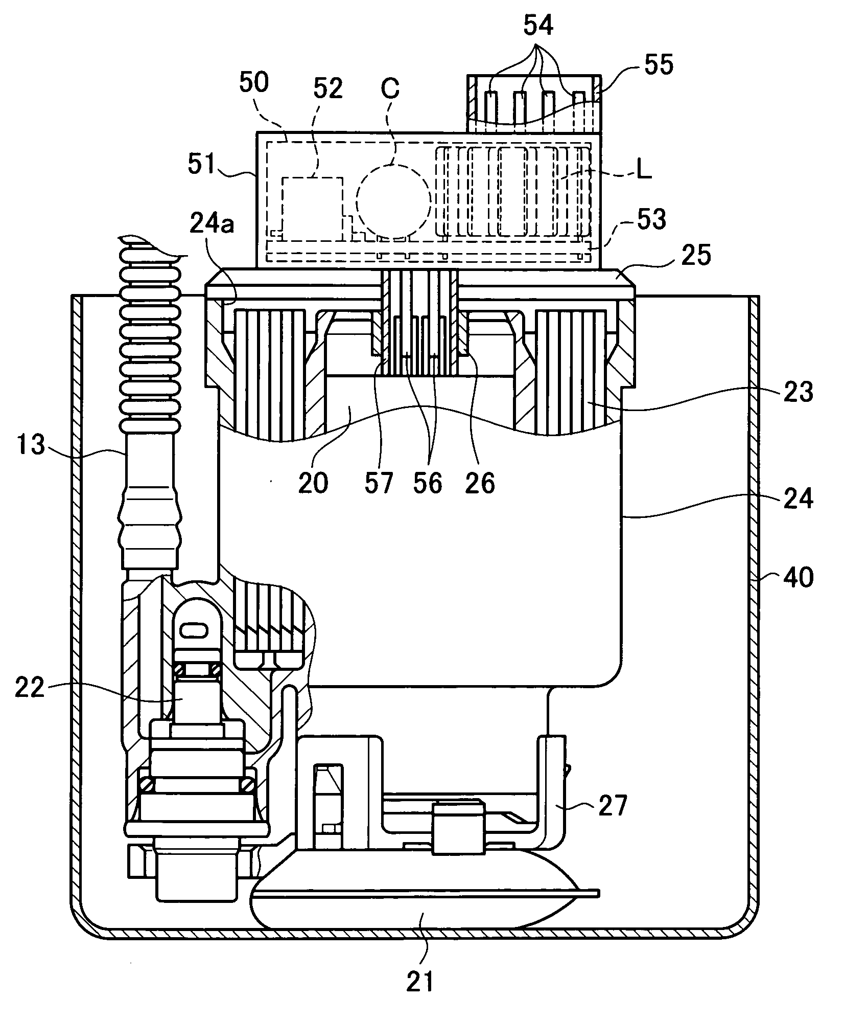
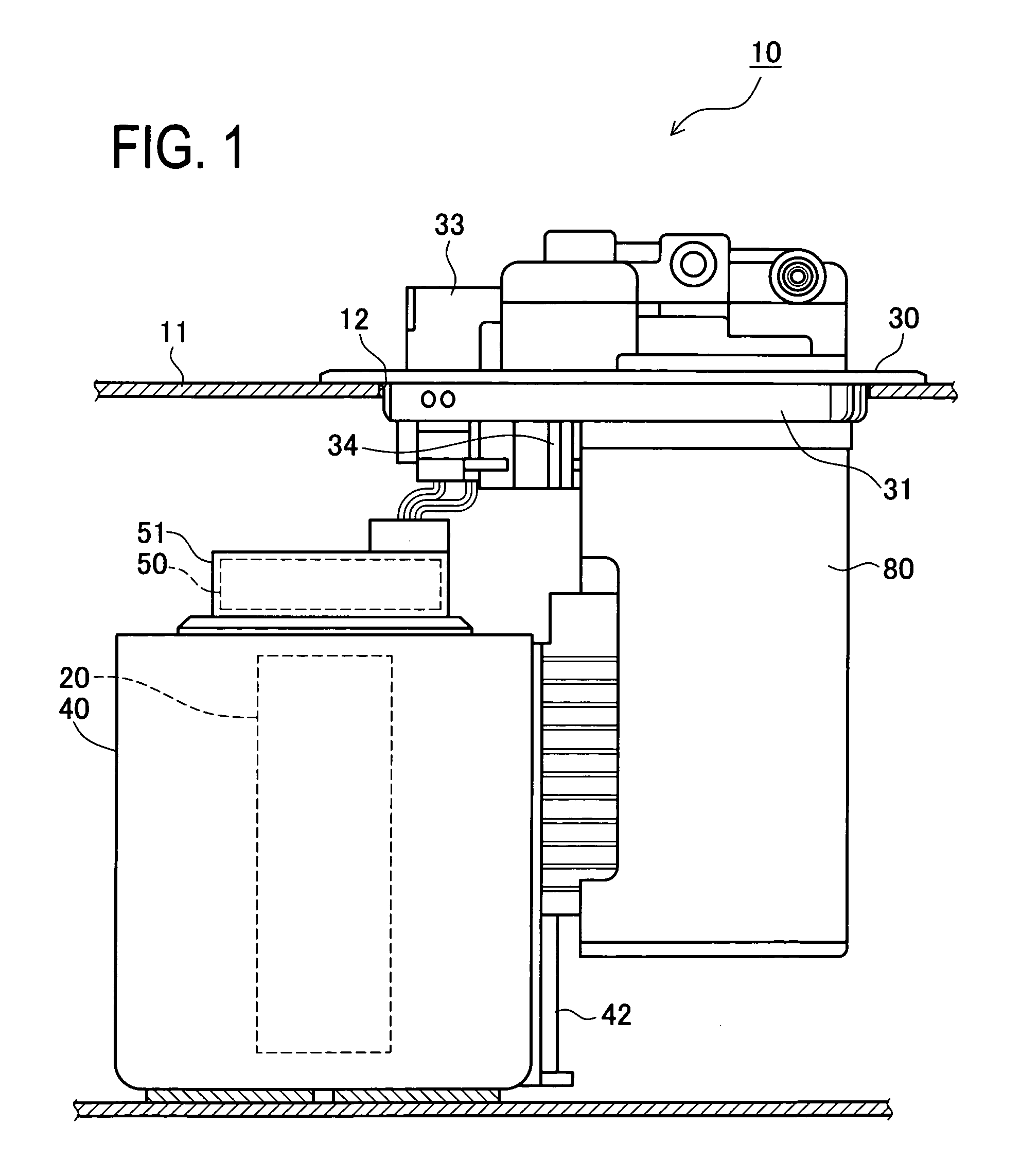
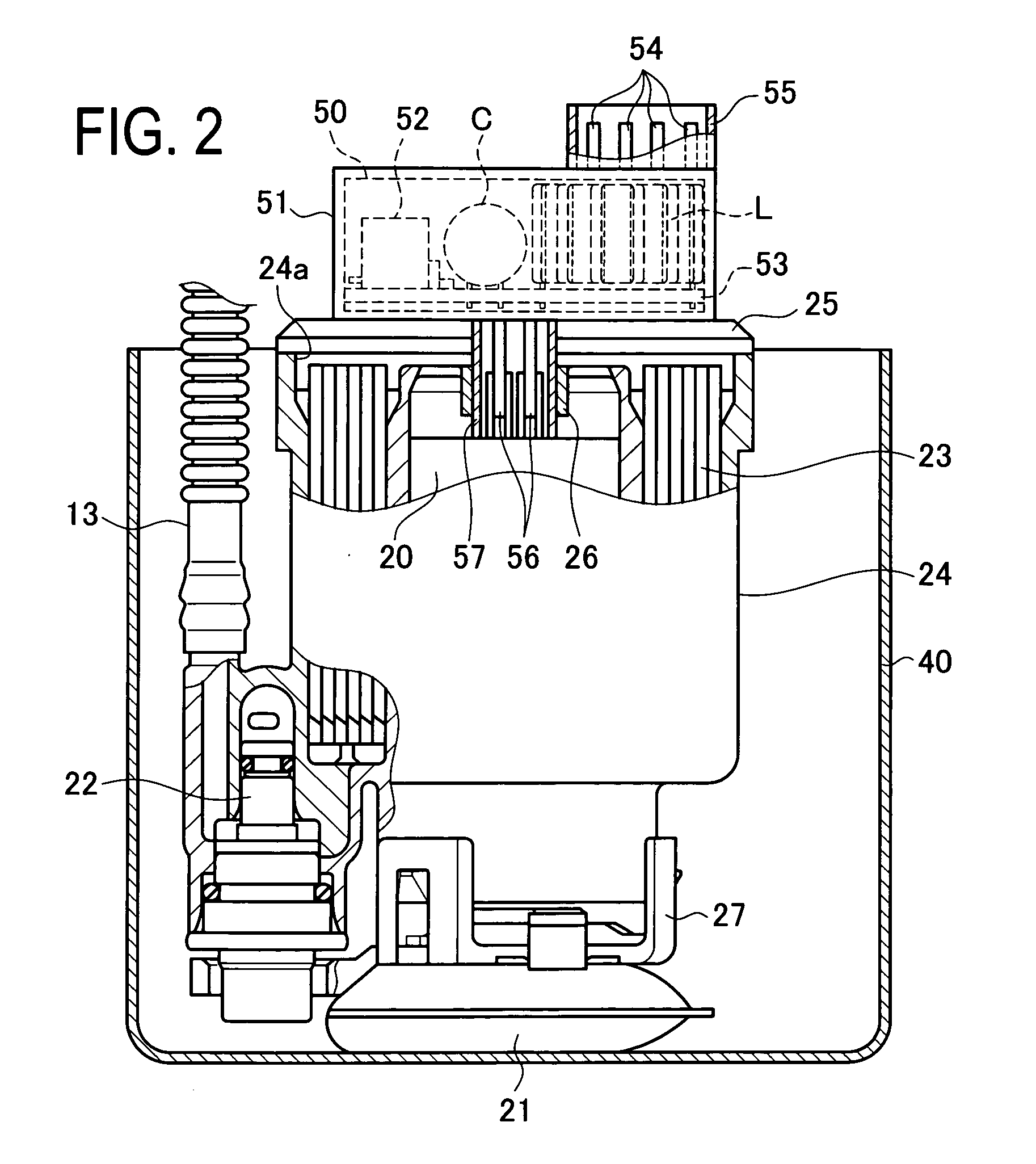
[0020]A first embodiment is first explained below. Thus, the following description is given to a fuel pump unit in the first embodiment with reference to FIGS. 1 to 3. FIG. 1 is a side view showing a schematic configuration of the fuel pump unit in the first embodiment. FIG. 2 is a partly sectional view showing a schematic configuration of the inside of a reserve cup and its surroundings. FIG. 3 is a plan view of the reserve cup and its surroundings.

[0021]As shown in FIG. 1, a fuel pump unit 10 is a combination of a set plate (a mounting plate) 30 placed to close a mounting hole 12 of a resin fuel tank 11, a reserve cup 40 internally holding a fuel pump 20 and others, and a canister 80. The fuel pump unit 10 is mounted in the fuel tank 11 in such a manner that the set plate 30 is attached to the fuel tank 11 so as to close the mounting hole 12 of the fuel tank 11.

[0022]The reserve cup 40 is a resin molded component having a bottom-closed cylindrical shape as shown in FIGS. 2 and 3. ...

embodiment 2

[0049]A second embodiment will be explained below. The second embodiment is almost the same in basic configuration as the first embodiment excepting that a controller case is designed to have a size almost equal to an opening of a reserve cup, and the reserve cup (cup height) is designed to be larger in height than that in the first embodiment. In the following description, similar parts or components to in the first embodiment are given the same reference codes and their explanations are omitted, and a fuel pump unit in the second embodiment is explained with a focus on differences from the first embodiment, referring to FIGS. 4 and 5. FIG. 4 is a plan view showing a schematic configuration of the reserve cup and its surroundings in the fuel pump unit in the second embodiment. FIG. 5 is a partly sectional view showing a schematic configuration of the reserve cup and its surroundings in the fuel pump unit in the second embodiment.

[0050]In the fuel pump unit in the second embodiment,...


PUM


Abstract

A fuel supply apparatus arranged to control supply of fuel includes a motor-driven fuel pump to be placed in a fuel tank, a mounting plate for closing a mounting hole of the fuel tank, a reserve cup that houses the fuel pump, and a pump controller adapted to control power supply to the fuel pump, and the pump controller is placed below the mounting plate and above the fuel pump.

Description

BACKGROUND OF THE INVENTION[0001]1. Field of the Invention[0002]The present invention relates to a fuel supply apparatus arranged to control operation of a fuel pump by a pump controller to control fuel supply.[0003]2. Description of Related Art[0004]Heretofore, a fuel supply apparatus integrally including a pump controller for controlling operation of a fuel pump (a controller-integrated fuel supply apparatus) has been known. This type of fuel supply apparatus is arranged such that the number of revolutions of the fuel pump is controlled by the pump controller to change an amount of fuel to be discharged from the fuel pump.[0005]One example of such fuel supply apparatus is disclosed in JP2004-332582A. This fuel supply apparatus is provided with a cover that covers an opening of a fuel tank, a motor-driven fuel pump placed in the fuel tank, a level gauge for detecting a liquid level of fuel in the fuel tank, a level gauge control circuit for processing an output signal of the level ...

Claims


Application Information

Patent Timeline
Patent Type & Authority Applications(United States)
IPC IPC(8): F02M37/04
CPCF02M37/0029F02M37/106F02M37/103F02M37/0082
Inventor TATEISHI, MAMORU
Owner AISAN IND CO LTD
Why Eureka
Try Eureka