Valve holding member

a technology of holding member and valve, which is applied in the direction of functional valve types, hose connections, couplings, etc., can solve the problems of increased manufacturing cost and weight of products, lack of resilience of arm parts, and difficulty in inserting valve holding members, etc., and achieves the effect of not substantially increasing the flow resistance of fluid passage and simple process

Active Publication Date: 2009-02-05
NITTO KOHKI CO LTD
View PDF2 Cites 5 Cited by
  • Summary
  • Abstract
  • Description
  • Claims
  • Application Information

AI Technical Summary

Benefits of technology

[0014]The valve holding member according to the present invention is fabricated by a simple process such as pressing. The valve holding member is reinforced in its structure, so that the valve holding member can be used

Problems solved by technology

However, due to its low stiffness, the valve holding member is mainly used for low-pressure and small-diameter pipe couplings, in which a biasing force of a coil spring acting on a valve is small.
However, if a thick sheet metal is used, the arm parts la

Method used


Image

  • Valve holding member
  • Valve holding member
  • Valve holding member

Examples


first embodiment

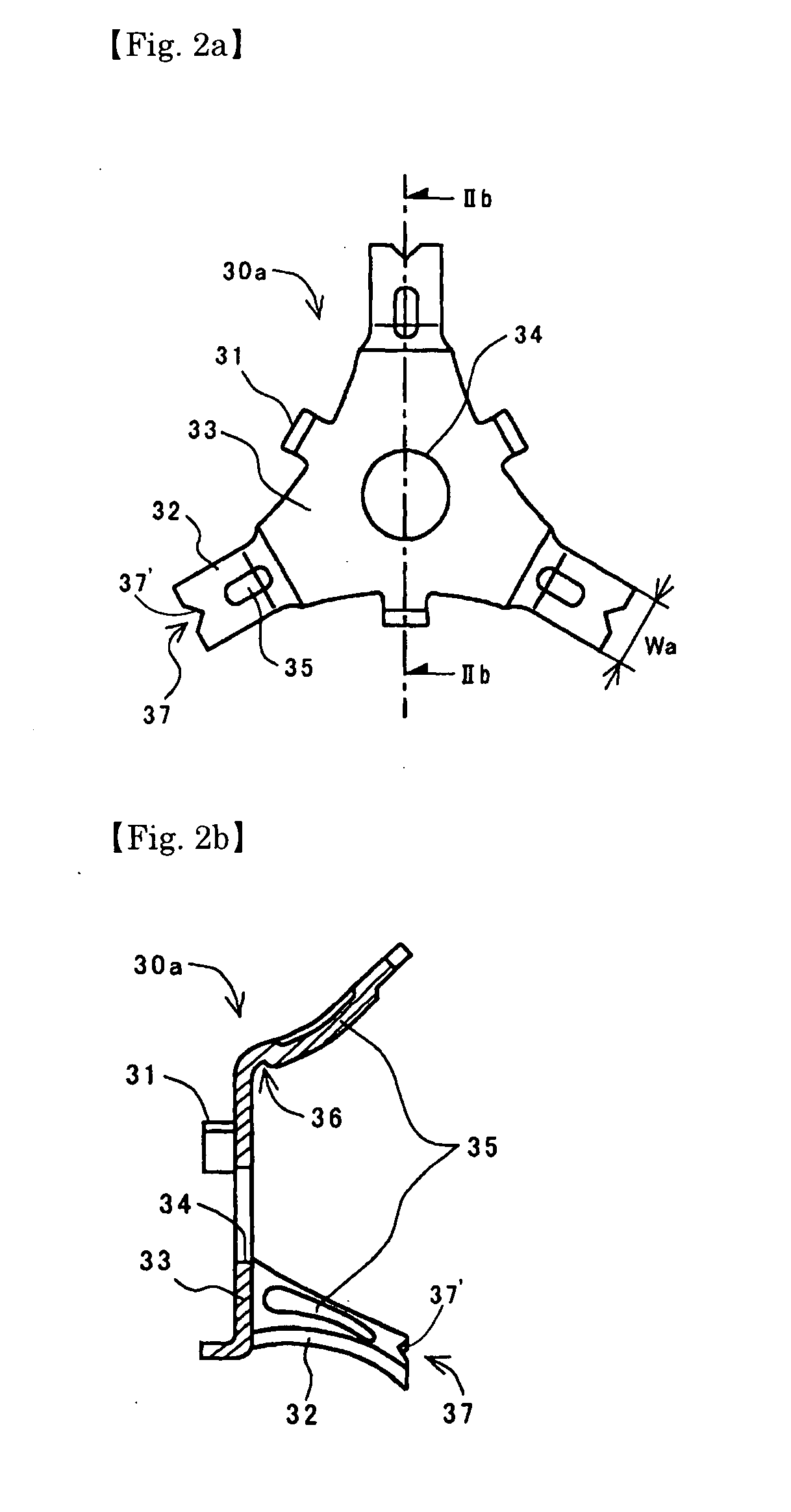
[0038]FIG. 2a is a front view of a valve holding member 30a according to the present invention. FIG. 2b is a sectional view taken along line IIb-IIb of FIG. 2a.

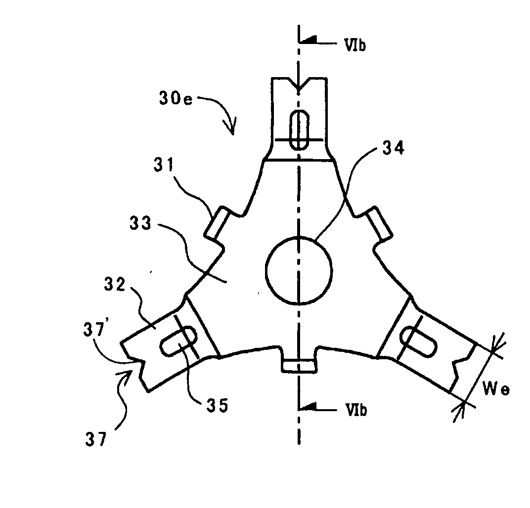
[0039]The valve holding member 30a comprises a hub part 33 provided at the center thereof with a guide hole 34 through which a valve stem extends, three arm parts 32 formed at the peripheral edge of the hub part at constant intervals and extending in the axial direction of the valve stem (rightward direction as viewed in FIG. 2b) and the radially outward direction with respect to the axis of the valve stem, and spring retaining parts 31 each provided between each adjacent pair of the arm parts 32 and extending from the hub part 33 in a direction axially opposite to that in which the arm parts 32 extend.

[0040]Each arm part 32 is provided, between the distal end 37 thereof and a connecting portion 36 between the hub part 33 and the arm part and formed with a reinforcing protrusion 35 extending in the longitudinal direction of ...

second embodiment

[0044]FIG. 3a is a front view of a valve holding member 30b according to the present invention. FIG. 3b is a sectional view taken along line IIIb-IIIb of FIG. 3a. The valve holding member 30b is characterized in that each reinforcing protrusion 35 is extended across each corresponding curved connecting portion 36 to each corresponding reinforcing protrusion 35b formed at the periphery of the hub part 33.

[0045]With this arrangement, the strength of the valve holding member 30b can be increased by approximately 5% compared to that of the valve holding member 30a of the first embodiment. The other configuration of the valve holding member 30b is substantially the same as that of the first embodiment, and the effect obtained by the configuration is also substantially the same. Like reference numerals are used to denote like structural elements in the valve holding member 30a of the first embodiment, and their description is omitted. (The same applies to the following embodiments.)

third embodiment

[0046]FIG. 4a is a front view of a valve holding member 30c according to the present invention. FIG. 4b is a sectional view taken along line IV-IV of FIG. 4a.

[0047]The valve holding member 30c is provided, at the peripheral edge of the guide hole 34, with a tubular reinforcing part 35c as a reinforcing structure extending in the axial direction, in which the arm parts 32 extend. When the valve holding member is set in a pipe coupling, the tubular reinforcing part 35c is set along the fluid passage direction, whereby an increase in the flow resistance of the fluid passage can be substantially restrained. Moreover, since the tubular reinforcing part 35c can be formed by pressing, it is possible to improve the strength of the valve holding member with little increase in cost. More specifically, the stiffness of the hub part 33 can be increased while the resilience of the arm parts 32 is maintained, whereby the area of the hub part 33 can be made smaller than the conventional type hub ...


PUM


Abstract

A valve holding member made of a sheet metal includes a hub part (33) having a guide hole (34) through which a valve stem (23) and a plurality of arm parts (32) formed at the peripheral edge of the hub part. The arm parts are extend from the peripheral edge in an axial direction and in a radially outward direction with respect to the axis of the valve stem. The valve holding member also includes any one of a first reinforcing protrusion (35) formed in at least one of the arm parts which extends along a longitudinal direction of the at least one arm part and protrudes radially outward or inward with respect to the axis of the valve stem, a tubular reinforcing part (35c,35e) formed around the guide hole and extending from the hub part in the axial direction, and a second reinforcing protrusion (35b) formed in the hub part and protruding in the axial direction.

Description

FIELD OF THE INVENTION[0001]The present invention relates to a valve holding member for holding a valve for opening and closing a fluid passage of a pipe coupling and, more particularly, to a valve holding member made of a single sheet metal.BACKGROUND OF THE INVENTION[0002]In a pipe coupling which employs a poppet valve for opening and closing a fluid passage, a valve holding member is used, which has a hub part through which a valve stem of the poppet valve passes, and a plurality of arm parts extending radially outwardly from the hub part and firmly engaging with the inner surface of the fluid passage to retain the hub part in the center of the fluid passage. The valve is set such that a valve head thereof is pressed against a valve seat formed on the inner surface of the fluid passage by means of a coil spring disposed around the valve stem and between the hub part and the valve head.[0003]The present applicant has filed an application related to a valve holding member character...

Claims


Application Information

Patent Timeline
IPC IPC(8): F16L55/00
CPCF16K15/18F16K15/026F16K15/063F16L55/07
Inventor NISHIO, TAKUYAYAMASHITA, JINSANADA, HIDEYUKI
Owner NITTO KOHKI CO LTD
Why Eureka
Try Eureka