LED Controller IC Using Only One Pin to Dim and Set a Maximum LED Current

a technology of led controller and controller, which is applied in the direction of instruments, light sources, electrical equipment, etc., can solve the problems of reducing the reliability of led or damage, incurring extra cost and board space penalties, and increasing the sink current , the effect of reducing the drive signal

Active Publication Date: 2009-02-05
MICREL
View PDF2 Cites 45 Cited by
  • Summary
  • Abstract
  • Description
  • Claims
  • Application Information

AI Technical Summary

Benefits of technology

[0013]Independent of setting the maximum current, a voltage proportional to the inverse of the duty cycle is output by a low pass filter. The low pass filter averages an inverted PWM signal. This average voltage drives a sinking or dimming current source that sinks (subtracts) some of the “maximum current” from the second current source, depending on the duty cycle. The resulting difference current is converted to a control voltage for the LED driver current sources. So, the current applied to each LED is a continuous current, where the maximum PWM duty cycle causes the sink current to be a minimum. Any decrease in the duty cycle increases the sink current and reduces the drive signal to the LED drivers. In this way, both the maximum current and the brightness control is controlled using only one pin of the IC.

Problems solved by technology

Any current exceeding this maximum rated current may reduce the reliability of the LED or damage it.
Although the technique of FIG. 2 requires the IC 26 to have only one pin for the current control, the technique has the drawback of requiring the user to employ three resistors in the output circuit, which incurs extra cost and board space penalties.

Method used


Image

  • LED Controller IC Using Only One Pin to Dim and Set a Maximum LED Current
  • LED Controller IC Using Only One Pin to Dim and Set a Maximum LED Current
  • LED Controller IC Using Only One Pin to Dim and Set a Maximum LED Current

Examples


Embodiment Construction

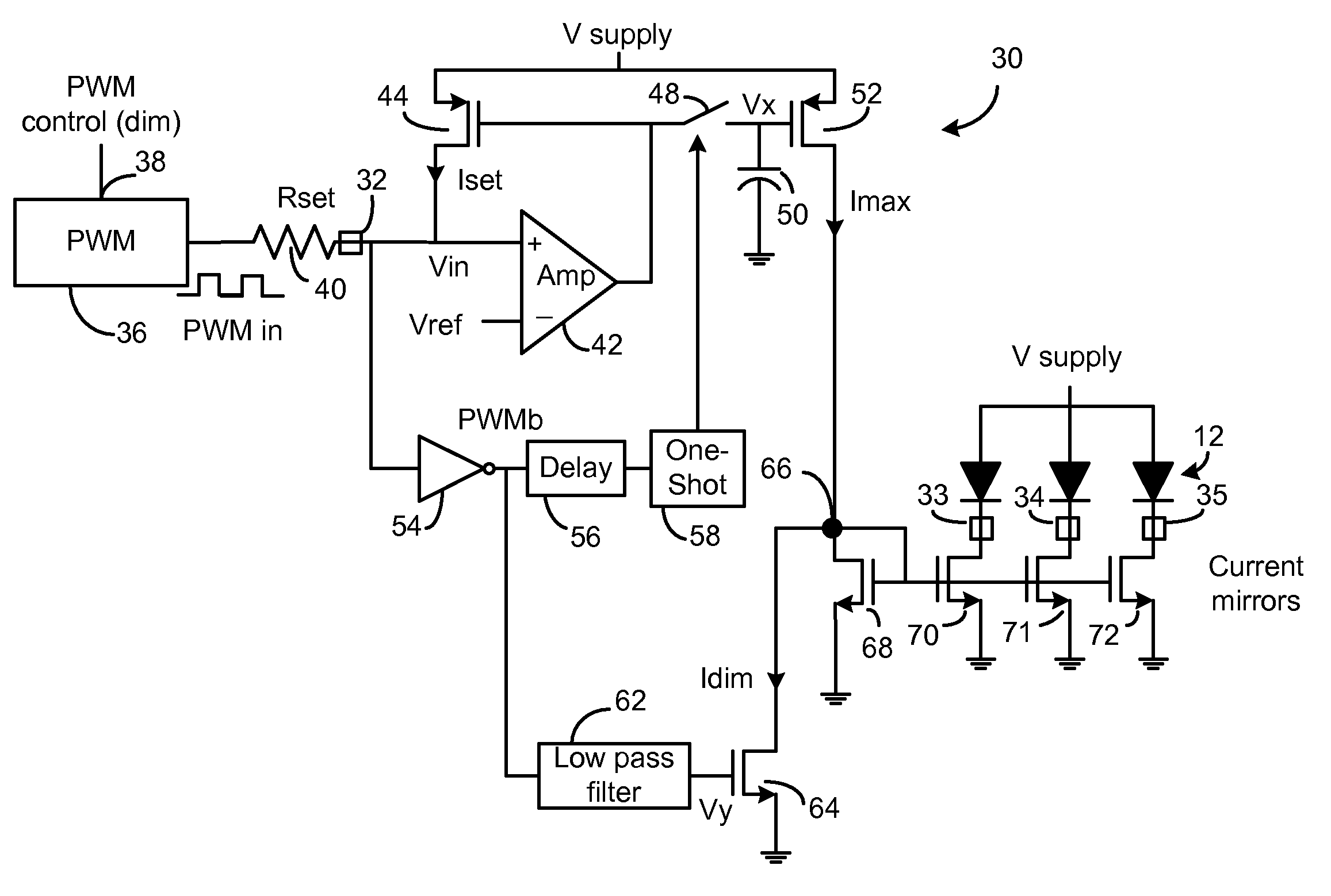
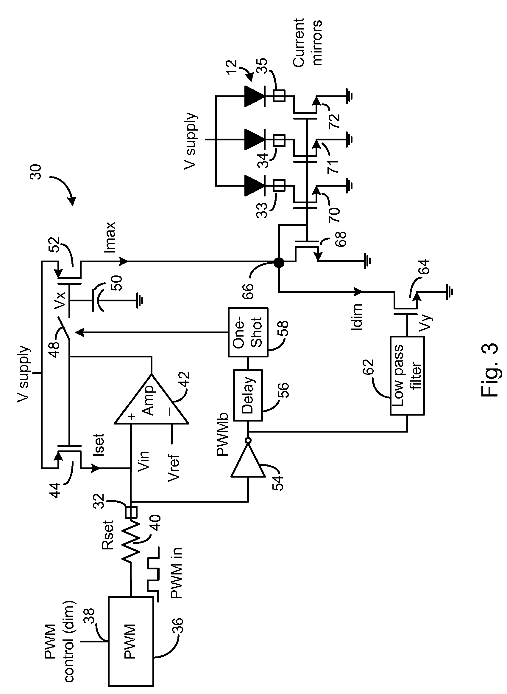
[0022]The LED driver IC of the present invention will be described with respect to FIGS. 3 and 4. The IC 30 package includes one pin 32 for both setting the maximum current through the LEDs 12 and for controlling the brightness of the LEDs. The IC 30 package also includes pins 33-35 for connection to the cathodes of the LEDs 12. In another embodiment, the components of the IC driver may be selected so that the pins 33-35 are connected to the anodes of the LEDs 12, and the cathodes are directly connected to ground.

[0023]Additional pins (not shown) on the IC 30 package are connected to the supply voltage and to ground.

[0024]A conventional external PWM source 36 outputs a pulse train having a frequency typically between 100 Hz-1 MHz, where the duty cycle (ratio of on time versus total time) determines the brightness levels of the LEDs 12. An oscillator internal to the PWM source 36 determines the frequency. Varying a control signal 38 into the PWM source 36 varies the duty cycle. The c...


PUM


Abstract

An LED driver IC is described that uses a single pin to both set the maximum current through one or more driven LEDs and variably control the brightness of the LEDs. A single resistor is connected to the control pin of the IC, where the value of the resistor sets the maximum current through the LEDs. A PWM source, outputting a pulse train at a particular duty cycle, is connected to the other end of the resistor, where the duty cycle controls the LED brightness level. When the PWM signal is low (e.g. ground), a sample and hold circuit connects the output of a feedback control voltage to an Imax current source to set a maximum current based on the external resistor value. An inverse of the duty cycle of the PWM controller controls a current Idim that is subtracted from the maximum current Imax set by the resistor. This difference current is used to control drivers for the LEDs.

Description

FIELD OF THE INVENTION[0001]This invention relates to light emitting diode (LED) drivers and, in particular, to a driver that sets a maximum current through one or more LEDs and also variably controls the brightness of the LEDs.BACKGROUND[0002]LEDs are typically driven by a current source. LEDs are usually characterized by the manufacturer as having a certain brightness level at a maximum rated current. Any current exceeding this maximum rated current may reduce the reliability of the LED or damage it. Accordingly, LED driver designers sometimes include a means for the customer to set the maximum current delivered to an LED, since the driver may be used with a variety of types of LED.[0003]LED drivers also typically enable the user to control the brightness level of the LED by controlling the continuous current level or controlling the average current level. The average current level can be controlled by controlling the duty cycle of current pulses to the LEDs. When controlling the ...

Claims


Application Information

Patent Timeline
Patent Type & Authority Applications(United States)
IPC IPC(8): H05B41/36
CPCH05B33/0848H05B33/0827H05B45/14H05B45/46
Inventor GATER, CHRISTIAN
Owner MICREL
Why Eureka
Try Eureka