Double ended inverter system with a cross-linked ultracapacitor network

a technology of cross-linked ultracapacitor network and inverter system, which is applied in the direction of motor/generator/converter stopper, multiple dynamo-motor starters, process and machine control, etc., can solve the problems of increasing the cost, weight, and complexity of the various electrical systems of automobiles, and increasing the complexity of the manufacturing of vehicles

Active Publication Date: 2009-02-05
GM GLOBAL TECH OPERATIONS LLC
View PDF6 Cites 60 Cited by
  • Summary
  • Abstract
  • Description
  • Claims
  • Application Information

AI Technical Summary

Benefits of technology

[0009]This summary is provided to introduce a selection of concepts in a simplified form that are further described below in the detailed description. This summary is not in...

Problems solved by technology

One of the changes involves the power usage and complexity of the various electrical systems within automobiles, particularly alternative fuel vehicles, such as hybrid, electric, and fuel cell vehicles.
However, the power sources (e.g., batteries) used in such applications provide onl...

Method used


Image

  • Double ended inverter system with a cross-linked ultracapacitor network
  • Double ended inverter system with a cross-linked ultracapacitor network
  • Double ended inverter system with a cross-linked ultracapacitor network

Examples


second embodiment

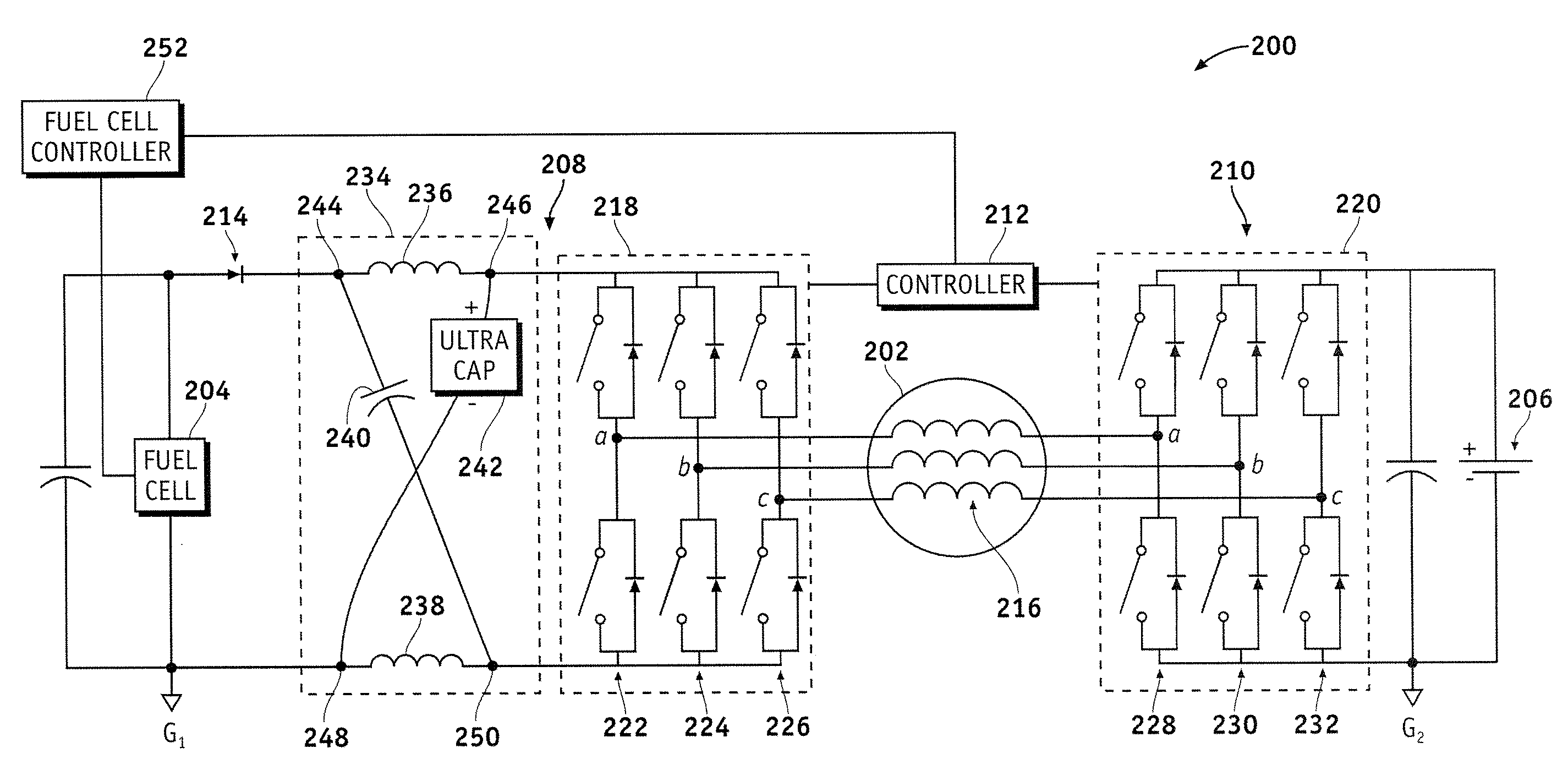
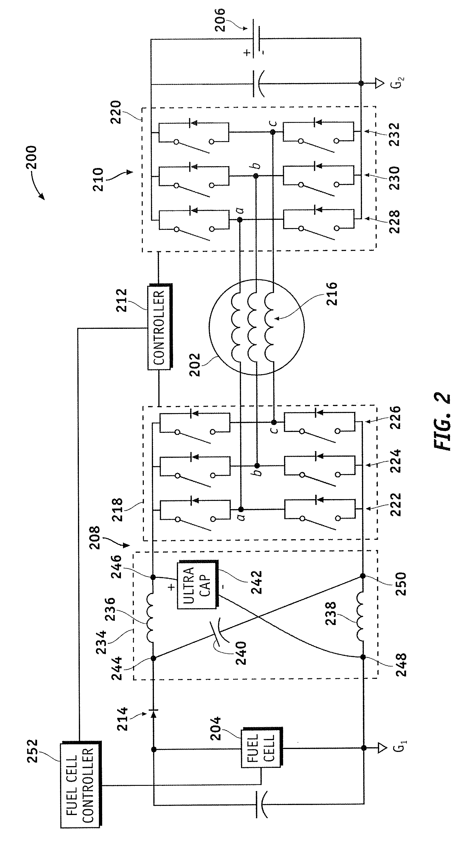
[0043]FIG. 3 is a schematic circuit representation of a double ended inverter system 300 suitable for use with an electric or hybrid electric vehicle. Double ended inverter system 300 is similar in many respects to double ended inverter system 200, and common features, operating characteristics, and elements will not be redundantly described here. Double ended inverter system 300 utilizes another ultracapacitor 302 in lieu of capacitance element 240. Although not a requirement, preferred embodiments can utilize a symmetrical topology where ultracapacitors 242 and 302 are matched. In other words, the capacitance, rating, and other electrical characteristics of ultracapacitors 242 and 302 are the same in preferred embodiments.

[0044]A controller 304 is suitably configured to operate double ended inverter system 300 such that both ultracapacitors can provide DC voltage for driving AC traction motor 202, and such that both ultracapacitors can be recharged as needed. Moreover, controller ...

third embodiment

[0045]FIG. 4 is a schematic circuit representation of a double ended inverter system 400 suitable for use with an electric or hybrid electric vehicle. Double ended inverter system 400 is similar in many respects to double ended inverter system 200, and common features, operating characteristics, and elements will not be redundantly described here. Double ended inverter system 400 employs an ultracapacitor 402 for the second DC energy source (rather than battery 206 as depicted in FIG. 2 and FIG. 3). Furthermore, double ended inverter system 400 employs a battery 404 in lieu of ultracapacitor 242.

[0046]A controller 406 is suitably configured to operate double ended inverter system 400 such that ultracapacitor 402 can provide DC voltage for driving AC traction motor 202, and such that ultracapacitor 402 can be recharged as needed. Moreover, controller 406 influences operation of inverter section 218 and inverter section 220 to manage power transfer among fuel cell 204, ultracapacitor ...


PUM


Abstract

A double ended inverter system for an AC traction motor of a vehicle includes a fuel cell configured to provide a DC voltage, an impedance source inverter subsystem coupled to the fuel cell, a DC voltage source, and an inverter subsystem coupled to the DC voltage source. The impedance source inverter subsystem, which includes an ultracapacitor, is configured to drive the AC traction motor. The inverter subsystem is configured to drive the AC electric traction motor. The ultracapacitor is implemented in a crossed LC network coupled to the fuel cell.

Description

CROSS-REFERENCE TO RELATED APPLICATION[0001]This application claims the benefit of U.S. provisional patent application Ser. No. 60 / 952,784, filed Jul. 30, 2007 (the entire content of which is incorporated by reference herein).TECHNICAL FIELD[0002]The subject matter described herein relates generally to an electric traction system. More particularly, the subject matter relates to a double ended inverter system, for use in a hybrid or electric vehicle, that includes an impedance source inverter and at least one ultracapacitor that provides additional energy for driving the vehicle.BACKGROUND[0003]In recent years, advances in technology, as well as ever evolving tastes in style, have led to substantial changes in the design of automobiles. One of the changes involves the power usage and complexity of the various electrical systems within automobiles, particularly alternative fuel vehicles, such as hybrid, electric, and fuel cell vehicles.[0004]Many of the electrical components, includi...

Claims


Application Information

Patent Timeline
IPC IPC(8): H02P27/06H02M7/44B60L50/15
CPCB60L11/005B60L11/1887Y02T90/34Y02T10/7022B60L11/1892B60L50/40B60L58/40B60L58/33Y02T10/70Y02T90/40
Inventor NAGASHIMA, JAMES M.WELCHKO, BRIAN A.CHAKRABARTI, SIBAPRASADPERISIC, MILUNSMITH, GREGORY S.JOHN, GEORGE
Owner GM GLOBAL TECH OPERATIONS LLC
Why Eureka
Try Eureka