Machine tool having function of correcting mounting error through contact detection

Active Publication Date: 2009-02-05
FANUC LTD
View PDF12 Cites 25 Cited by
  • Summary
  • Abstract
  • Description
  • Claims
  • Application Information

AI Technical Summary

Benefits of technology

[0016]The correction means may automatically correct the mounting error of the workpiece or the machining attachment by rotating the rotary axis on which the workpiece or the machining attachment is mounted in an opposite direction by an angle of the determined inclination.
[0017]The correction means may automatically correct machining coordinate values of the machining program in accordance with the determined inclination.
[0018]According to the present invention, the orientation of the workpiece or the machining attachment can be easily and automatically corrected by rotating the workpiece or the machining attachment based on position command values specified by an

Problems solved by technology

Also, where the surface of a brittle material needs to be directly traced in order to position the material in parall

Method used


Image

  • Machine tool having function of correcting mounting error through contact detection
  • Machine tool having function of correcting mounting error through contact detection
  • Machine tool having function of correcting mounting error through contact detection

Examples


Embodiment Construction

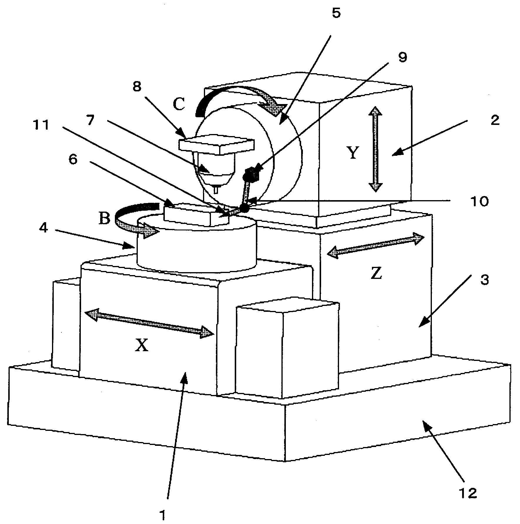
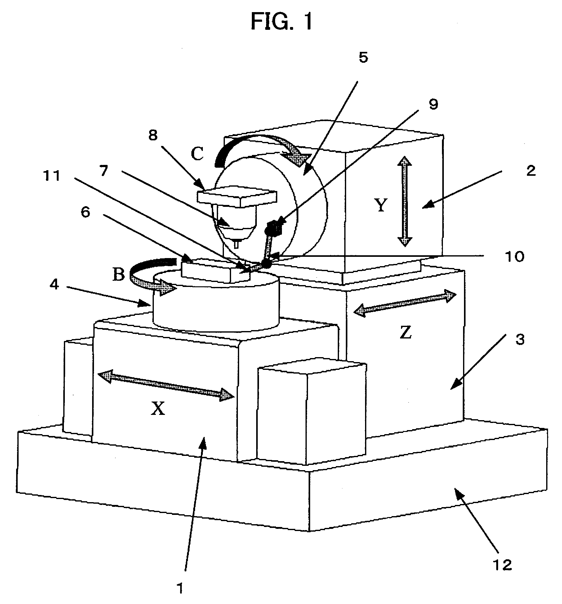
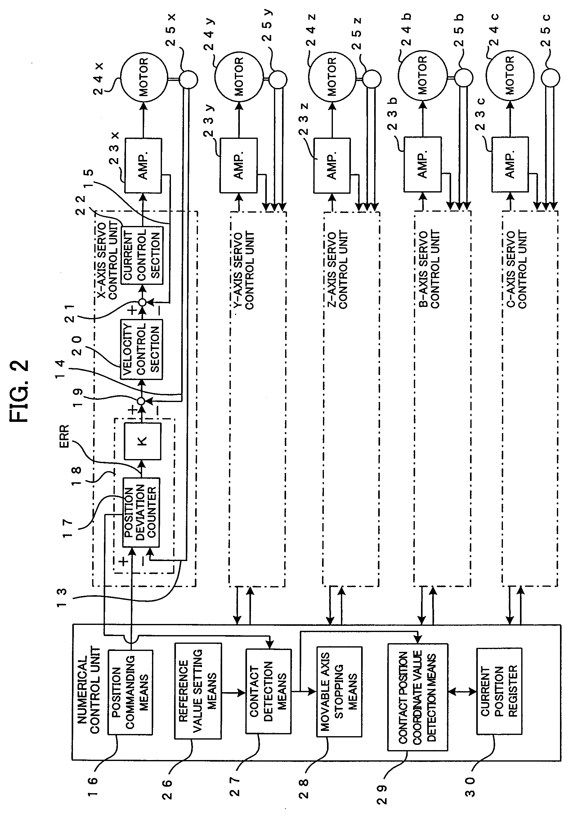
[0038]FIG. 1 is a perspective view of a principal part of a machine tool according to an embodiment of the present invention, which has a function of automatically correcting a mounting error through contact detection. The machine tool of this embodiment is a machine tool with five simultaneously controllable axes, namely, X, Y and Z axes, which are linear axes, and B and C axes, which are rotary axes. These movable axes are each supported by a fluid bearing, not shown, and thus are free from solid friction (mechanical friction). The rotary axes are directly coupled to respective motors to be directly driven thereby. As shown in FIG. 2, the linear X, Y and Z axes are associated with servomotors 24x, 24y and 24z, respectively, each comprising a linear motor, and movements of movable members driven by the respective servomotors 24x, 24y and 24x are detected by position / velocity detectors 25x, 25y and 25z, respectively, each comprising a linear scale.

[0039]Specifically, the position de...


PUM


Abstract

A machine tool capable of automatically correcting an orientation of a workpiece or machining attachment based on detection results from position detectors that the machine tool inherently has. The machine tool comprises: position detectors; position deviation determining means; contact detection means that detects a contact between a probe and a surface of the workpiece or the machining attachment based on a position deviation; movable axis stopping means; coordinate value detection means; inclination determining means; and correction means. The inclination determining means moves linear axes to perform detection of contacts between the probe and the surface of the workpiece or the machining attachment at least two different points, and determines an inclination of the workpiece or the machining attachment using the obtained coordinate values. The correction means corrects a mounting error of the workpiece or the machining attachment, or corrects the machining program based on the determined inclination.

Description

BACKGROUND OF THE INVENTION[0001]1. Field of the Invention[0002]The present invention relates to machine tools, and more particularly to a machine tool having the function of correcting a mounting error through contact detection.[0003]2. Description of Related Art[0004]As techniques for detecting inclination of a workpiece to be cut by a cutting machine, there has been known a technique in which a displacement detector is brought into contact with a reference plane of the workpiece or of a machining attachment and then the reference plane is traced with the displacement detector to acquire data about the inclination. According to this technique, the rotary axis on which the workpiece or the machining attachment is mounted is manually moved in accordance with the acquired data, by using the operator's panel or the like, to adjust the orientation of the workpiece. After the adjustment, the displacement detector is again brought into contact with the reference plane of the workpiece or...

Claims


Application Information

Patent Timeline
IPC IPC(8): G05B1/06
CPCG05B19/402G05B19/4083G05B2219/50046G05B2219/37405G05B2219/37593G05B2219/36503
Inventor HON, YONPYOEBIHARA, KENZOKAWAI, TOMOHIKO
Owner FANUC LTD
Why Eureka
Try Eureka