Liquid Crystal Display Device

a display device and liquid crystal technology, applied in static indicating devices, instruments, non-linear optics, etc., can solve the problems of reducing color reproducibility, reducing aperture ratio, and affecting the display quality, so as to achieve the effect of increasing the aperture ratio

Active Publication Date: 2009-02-05
PANASONIC LIQUID CRYSTAL DISPLAY CO LTD +1
View PDF4 Cites 31 Cited by
  • Summary
  • Abstract
  • Description
  • Claims
  • Application Information

AI Technical Summary

Benefits of technology

[0026]With the effect to be achieved by the typical aspects of the invention described in this appli...

Problems solved by technology

If no light-shielding film is provided, the matching displacement during manufacturing causes color mixture between subpixels of different colors, thereby considerably degrading the display qua...

Method used


Image

  • Liquid Crystal Display Device
  • Liquid Crystal Display Device
  • Liquid Crystal Display Device

Examples


first embodiment

[0052]In a first embodiment, described is an example of applying the invention to a transmissive liquid crystal display device of IPS mode.

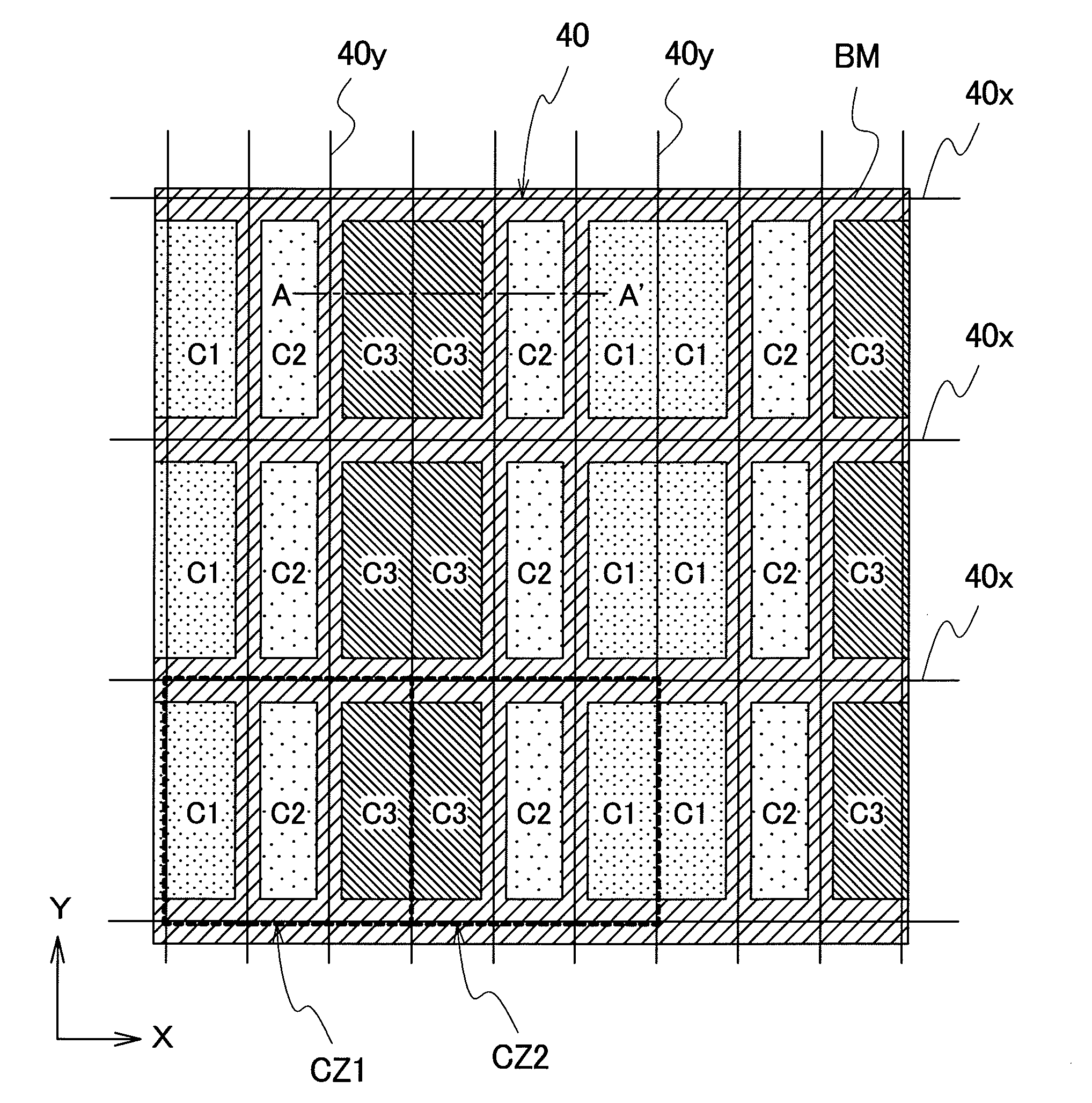
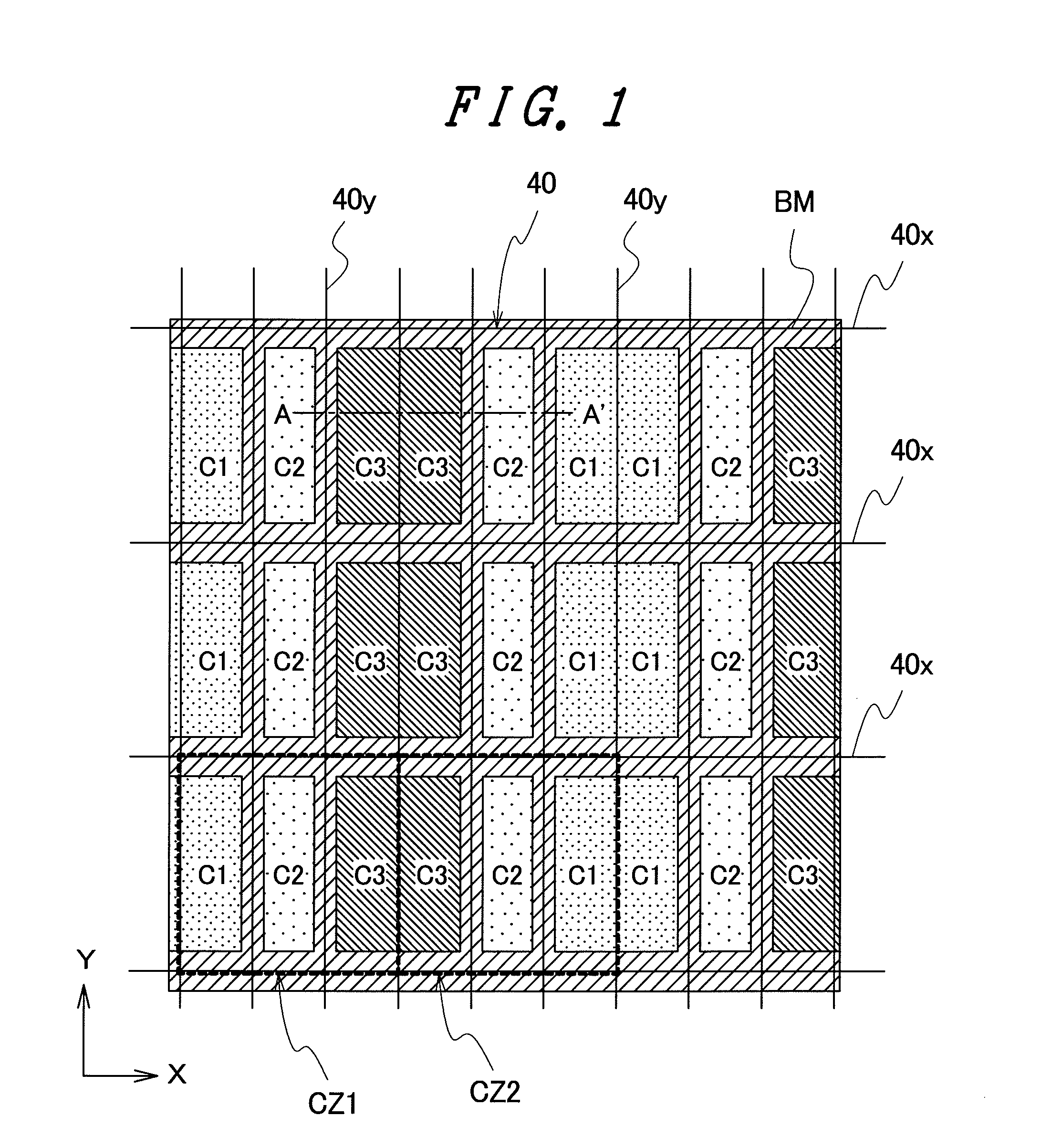
[0053]FIGS. 1 to 4 are each a diagram showing a transmissive liquid crystal display device of IPS mode in the first embodiment of the invention, i.e., FIG. 1 is a plan view of a liquid crystal display panel showing the layout of color filters, FIG. 2 is a plan view of the liquid crystal display panel showing pixel electrodes and opposing electrodes on the side of a TFT substrate, FIG. 3 is a plan view of the liquid crystal display panel showing the pixel electrodes, scan lines, and video lines on the side of the TFT substrate, and FIG. 4 is a cross-sectional view of the liquid crystal display panel showing the cross-sectional configuration thereof cut along a line A-A′ of FIG. 1.

[0054]The transmissive liquid crystal display device of IPS mode in the first embodiment is provided with a liquid crystal display panel 51 of FIG. 4. As shown in FIG. 4,...

second embodiment

[0093]FIGS. 5 and 6 are each a diagram showing a transmissive liquid crystal display device of IPS mode in a second embodiment of the invention. Specifically, FIG. 5 is a plan view of a liquid crystal display panel, showing pixel electrodes and opposing electrodes on the side of a TFT substrate thereof, and FIG. 6 is a plan view of the liquid crystal display panel, showing the pixel electrodes, scan lines, and video lines thereof.

[0094]The transmissive liquid crystal display device of IPS mode in the second embodiment is basically of the same configuration as that of the first embodiment described above, but is different therefrom as below.

[0095]That is, as to the first embodiment described above, in the first and second subpixels 40a and 40b of the same color being adjacent to each other along the direction of the display lines, i.e., direction of X, in each of the pixel electrodes (PIX) of the first and second subpixels 40a and 40b, at least one of the liner portions 21 is overlai...

third embodiment

[0098]FIG. 7 is a plan view of a transmissive liquid crystal display device of IPS mode in a third embodiment of the invention, showing pixel electrodes, scan lines, and video lines of a liquid crystal display panel.

[0099]The transmissive liquid crystal display device of IPS mode in the third embodiment is basically of the same configuration as that of the first embodiment described above, but is different therefrom as below.

[0100]That is, in the first embodiment described above, in the first and second subpixels 40a and 40b of the same color being adjacent to each other along the direction of the display lines, i.e., direction of X, as shown in FIG. 3, a video line (DL1) for supply of a video signal to the pixel electrode (PIX) of the first subpixel 40 (40a) is disposed to overlay on, when viewed from above, a pixel boundary (40y1) between the first subpixel 40 (40a) and the second subpixel 40 (40b) adjacent thereto. Also as shown in FIG. 3, a video line (DL2) for supply of a video...


PUM


Abstract

A liquid crystal display panel is provided with a light-shielding film, and a plurality of subpixels arranged in a matrix. The subpixels each include a first electrode formed on a first substrate, a second electrode formed to be located upper than the first electrode, and a color filter formed on a second substrate. The second electrode has a plurality of linear portions. The subpixels are disposed adjacently along the direction of display lines, and any two of the adjacent subpixels have the same color of color filter. The light-shielding film is formed on the second substrate not to cover the pixel boundary between the two adjacent subpixels but to cover pixel boundaries of the remaining subpixels. The second electrodes of the two adjacent subpixels are formed separately, and assuming that the two adjacent subpixels are first and second subpixels, at least the second electrode of the first subpixel is disposed also to an area of the second subpixel beyond the pixel boundary between the first and second subpixels. Such a configuration favorably increases an aperture ratio of a liquid crystal display device including a color filter.

Description

BACKGROUND OF THE INVENTION[0001]1. Field of the Invention[0002]The present invention relates to a liquid crystal display device and, more specifically, to a technology that is effective when applied to a liquid crystal display device including a color filter.[0003]2. Background Art[0004]For color display, a liquid crystal display device is provided with a color filter irrespective of display mode. The colors used for a color filter basically include red (R), green (G), and blue (B), and these three colors of red, green, and blue configure a basic unit, i.e., a pixel.[0005]The invention relates to a liquid crystal display device including a color filter, and the related art of the invention includes the technologies of JP-A-11-84365, JP-A-2002-107709, and JP-A-2005-62220.[0006]The technologies described in JP-A-11-84365, JP-A-2002-107709, and JP-A-2005-62220 are those for arrangement of subpixels in order of RGBBGR.[0007]The issue here is that such related art, i.e., JP-A-11-84365, ...

Claims


Application Information

Patent Timeline
IPC IPC(8): G02F1/1343G02F1/1335
CPCG02F2001/136222G02F1/134363G02F1/136222
Inventor TANNO, JUNJIIGETA, KOICHI
Owner PANASONIC LIQUID CRYSTAL DISPLAY CO LTD
Why Eureka
Try Eureka