Magnetic recording medium, recording /reproducing apparatus, and stamper

a recording medium and recording/reproducing technology, applied in the field of magnetic recording medium, recording/reproducing apparatus, and stamper, can solve the problems of difficult to reliably read magnetic signals, thick residue covering of convex parts, and risk of excessive etching of convex parts, etc., to achieve favorable smoothness and read reliably

Inactive Publication Date: 2009-02-05
TDK CORPARATION
View PDF15 Cites 10 Cited by
  • Summary
  • Abstract
  • Description
  • Claims
  • Application Information

AI Technical Summary

Benefits of technology

[0013]On the above magnetic recording medium, by forming the at least one concave part in the servo pattern region so that a larger of an inscribed circle with a largest diameter out of inscribed circles on protruding end surfaces of the convex parts formed in the address pattern region and an inscribed circle with a largest diameter out of inscribed circles on protruding end surfaces of the convex parts formed in the burst pattern region is an inscribed circle with a largest diameter out of inscribed circles on protruding end surfaces of the convex parts formed in the servo pattern region, since no convex parts with wide protruding end surfaces that can have an inscribed circle with a diameter that exceeds the diameter of the larger inscribed circle are present inside the servo pattern region, when the layer of non-magnetic material formed so as to cover the concave / convex pattern inside the servo pattern region is etched, a situation where thick residue remains on the convex parts is avoided. By doing so, it is possible to provide a magnetic recording medium which has favorable smoothness inside the servo pattern region and from which servo data can be reliably read.
[0027]On this stamper, by forming a concave / convex pattern including at least one convex part formed corresponding to the at least one concave part in the concave / convex pattern on any of the magnetic recording media described above and a plurality of concave parts formed corresponding to the respective convex parts in the concave / convex pattern of such magnetic recording medium, when carrying out imprinting on a preform for manufacturing a magnetic recording medium, for example, it is possible to avoid a situation where convex parts with excessively wide protruding end surfaces that can have an inscribed circle with a larger diameter than an inscribed circle with a largest diameter out of inscribed circles on protruding end surfaces of the convex parts formed in the address pattern region or the burst pattern region are formed in the servo pattern region. This means that by etching the preform using the concave / convex pattern as a mask, it is possible to avoid a situation where convex parts with wide protruding end surfaces that can have an inscribed circle with a larger diameter than the inscribed circle with the largest diameter described above are formed inside the servo pattern region. Accordingly, when etching the layer of non-magnetic material formed so as to cover the concave / convex pattern, it is possible to avoid a situation where thick residue is produced on the convex parts inside the servo pattern region. By doing so, it is possible to manufacture a magnetic recording medium which has favorable smoothness and from which servo data can be read reliably. Also, since no concave parts that are excessively wide are present on the stamper corresponding to the protruding end surfaces of the convex parts of the magnetic recording medium, when the concave / convex pattern of the stamper is pressed onto a resin layer of a preform (a layer for forming a concave / convex pattern by imprinting), it is possible to avoid a situation where the convex parts are insufficiently high (i.e., the resin mask is insufficiently thick) due to an insufficient amount of resin material (the resin layer) moving into the concave parts of the stamper. Accordingly, when the preform is etched with the concave / convex pattern formed on the preform as a mask, it is possible to avoid a situation where the convex parts used as the mask disappear before the etching of the preform is complete, and as a result, it is possible to form a concave / convex pattern with at least one sufficiently deep concave part in the preform.

Problems solved by technology

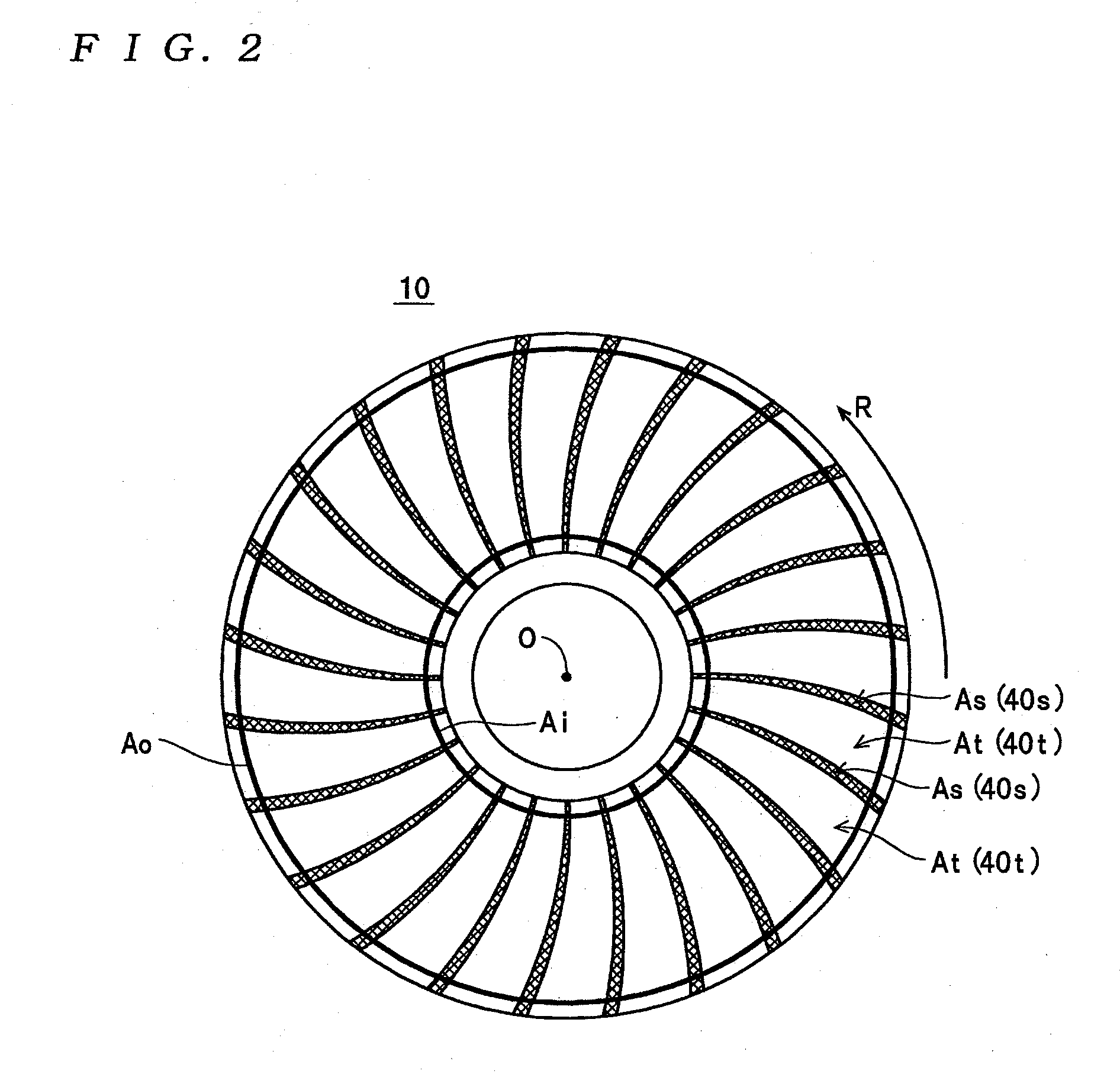
However, when a magnetic disk is manufactured according to this method of manufacturing, when dry etching is carried out, there are cases where a large amount of non-magnetic material (hereinafter, non-magnetic material remaining on the convex parts is also referred to as “residue”) remains on the convex parts with wide protruding end surfaces (for example, “long” convex parts where both the length in the direction of rotation of the magnetic disk and the length in the radial direction are long), resulting in the convex parts being thickly covered with residue.
Accordingly, when the dry etching continues until the residue on the convex parts 40az is completely removed across the entire range of the servo pattern regions Asz including the non-servo signal regions Axz, Axbz, there is the risk of excessively etching the convex parts 40az in the concave / convex patterns inside the preamble pattern regions Apz and the concave / convex patterns inside the address pattern regions Aaz where the lengths along the direction of rotation and the lengths along the radial direction of the protruding end surfaces are comparatively short, which can make it difficult to read magnetic signals reliably.

Method used


Image

  • Magnetic recording medium, recording /reproducing apparatus, and stamper
  • Magnetic recording medium, recording /reproducing apparatus, and stamper
  • Magnetic recording medium, recording /reproducing apparatus, and stamper

Examples


Embodiment Construction

[0064]Preferred embodiments of a magnetic recording medium, a recording / reproducing apparatus, and a stamper according to the present invention will now be described with reference to the attached drawings.

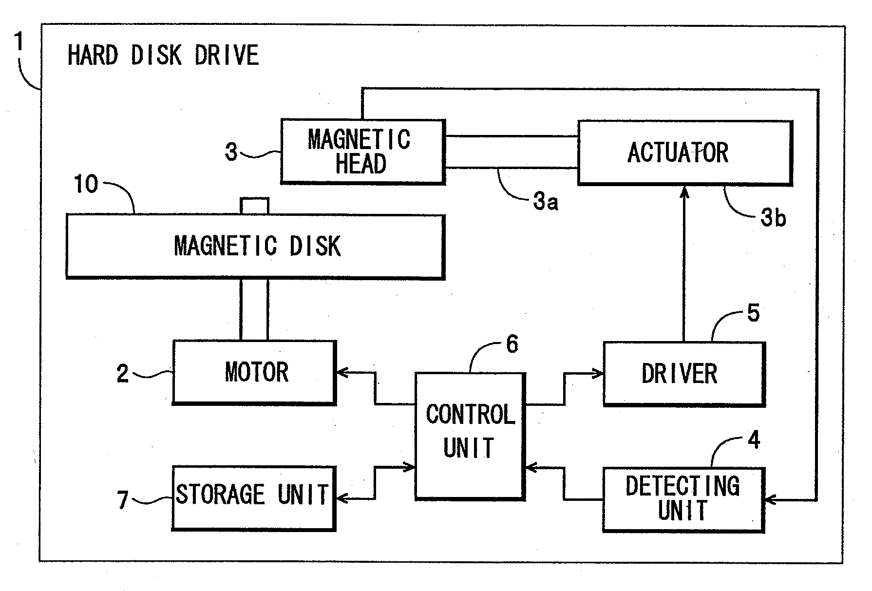
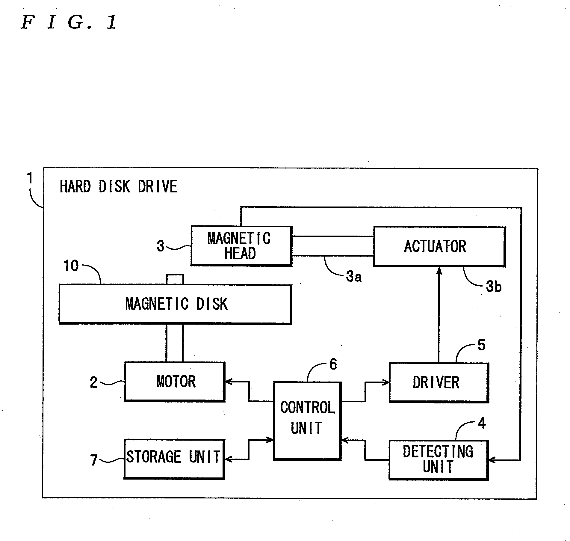
[0065]A hard disk drive 1 shown in FIG. 1 is one example of a recording / reproducing apparatus according to the present invention and includes a motor 2, a magnetic head 3, a detecting unit 4, a driver 5, a control unit 6, a storage unit 7, and a magnetic disk 10 so as to be capable of recording and reproducing various kinds of data. According to control by the control unit 6, the motor 2 rotates the magnetic disk 10 at a fixed speed, for example, 4200 rpm. The magnetic head 3 is attached to an actuator 3b via a swing arm 3a and is caused to move above the magnetic disk 10 by the actuator 3b during the recording and reproducing of data on the magnetic disk 10. Also, the magnetic head 3 carries out the reading of servo data from a servo pattern region As of the magnetic disk 10 (see...


PUM

PropertyMeasurementUnit
thicknessaaaaaaaaaa
thicknessaaaaaaaaaa
thicknessaaaaaaaaaa

Abstract

A servo pattern is formed in a servo pattern region on at least one surface of a substrate of a magnetic recording medium by a concave / convex pattern including a plurality of convex parts, at least protruding end parts of which are formed of magnetic material, and at least one concave part. The servo pattern region includes an address pattern region and a burst pattern region. The at least one concave part is formed in the servo pattern region so that a larger of an inscribed circle with a largest diameter out of inscribed circles on protruding end surfaces of the convex parts formed in the address pattern region and an inscribed circle with a largest diameter out of inscribed circles on protruding end surfaces of the convex parts formed in the burst pattern region is an inscribed circle with a largest diameter out of inscribed circles on protruding end surfaces of the convex parts formed in the servo pattern region.

Description

[0001]The present application is a continuation application of pending U.S. patent application Ser. No. 11 / 345,514, filed on Feb. 2, 2006, the entire contents of which is herein incorporated by reference.BACKGROUND OF THE INVENTION[0002]1. Field of the Invention[0003]The present invention relates to a magnetic recording medium where a servo pattern is formed by a concave / convex pattern in a servo pattern region, a recording / reproducing apparatus equipped with the magnetic recording medium, and a stamper for manufacturing the magnetic recording medium.[0004]2. Description of the Related Art[0005]As one example of a recording / reproducing apparatus equipped with this kind of magnetic recording medium, a magnetic recording apparatus equipped with a discrete track-type magnetic disk is disclosed by Japanese Laid-Open Patent Publication No. H09-097419. The magnetic disk provided in the magnetic recording apparatus is constructed by forming concentric recording tracks (“belt-shaped convex ...

Claims


Application Information

Patent Timeline
Patent Type & Authority Applications(United States)
IPC IPC(8): G11B5/596
CPCG11B5/59633G11B5/865G11B5/82
Inventor SOENO, YOSHIKAZUSUWA, TAKAHIRO
Owner TDK CORPARATION
Why Eureka
Try Eureka