Energy-Absorbing Textile Structure, in Particular for Use in Vehicle Construction and Method for Producing Said Structure

Inactive Publication Date: 2009-02-05
SGL KUMPERS GMBH & CO KG
View PDF5 Cites 7 Cited by
  • Summary
  • Abstract
  • Description
  • Claims
  • Application Information

AI Technical Summary

Benefits of technology

[0013]It has been shown that a triple change in direction of the standing ends produces a very clear reduction in the load peak, so no excessively high starting deceleration occurs.
[0014]A change in the braiding angle also leads to a local change in the structure. However, a change in the braiding angle alone is only noticeably effective if the deviation in the angle is relatively significant. It is therefore sensible to combine the change in the braiding angle with a change in the direction of the standing ends. In principle, the extent of the effect on the weakening of the structure also changes with the extent of the respective change. Therefore a virtually tailor-made construction for the respective application can be produced by using the invention. The selection of the yam materials in the standing end and in the braid

Problems solved by technology

However, these metallic structures have the drawback of a high weight in relation to the energy absorption.
The energy-absorbing structures made of high-tensile textile materials are, however, not plastically deformed like the metallic materials, but if appropriate provision is not made, may abruptly fail at a random weak point without absorbing energy to a significant extent.
This measure is relatively expensi

Method used


Image

  • Energy-Absorbing Textile Structure, in Particular for Use in Vehicle Construction and Method for Producing Said Structure
  • Energy-Absorbing Textile Structure, in Particular for Use in Vehicle Construction and Method for Producing Said Structure
  • Energy-Absorbing Textile Structure, in Particular for Use in Vehicle Construction and Method for Producing Said Structure

Examples


Embodiment Construction

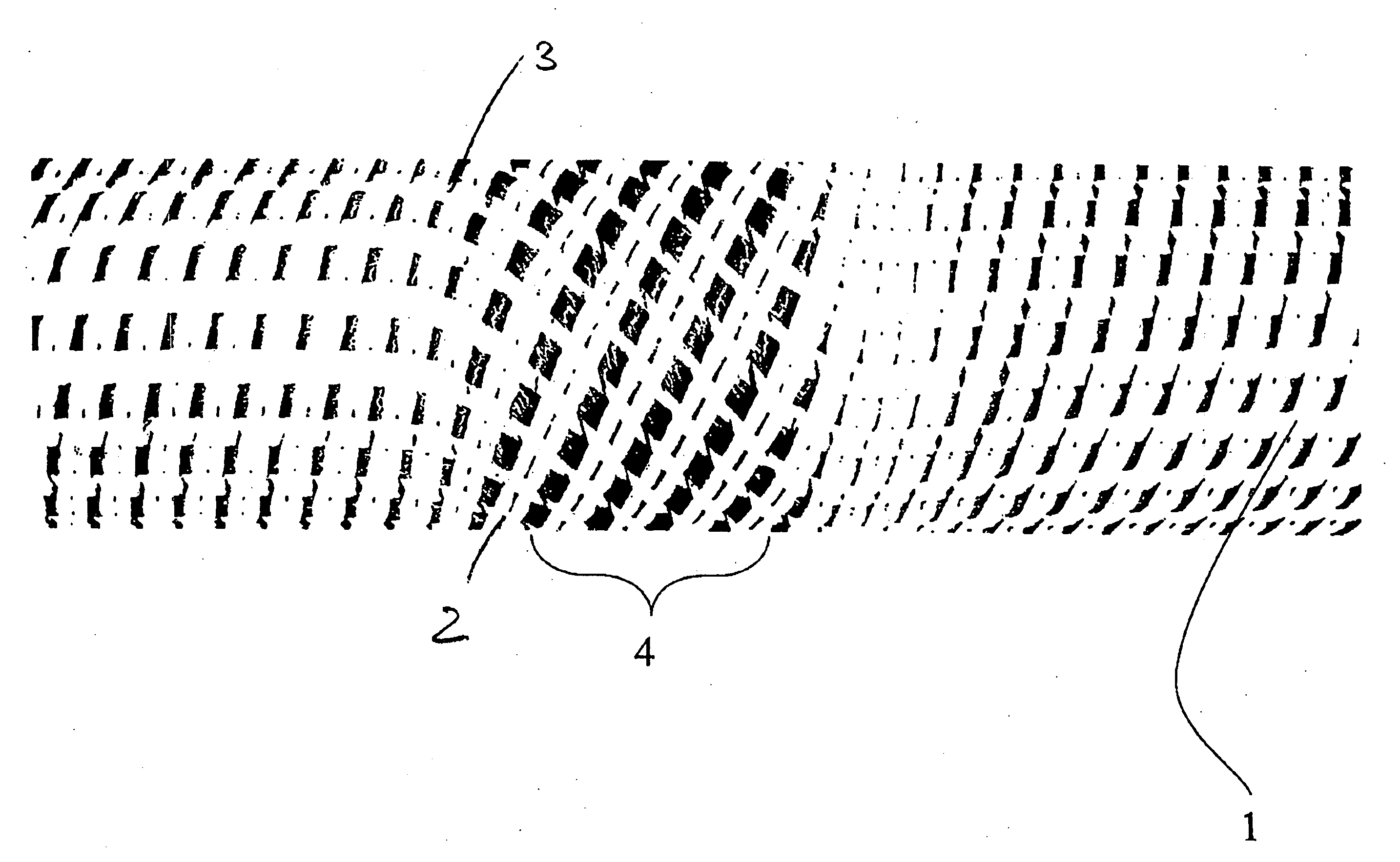
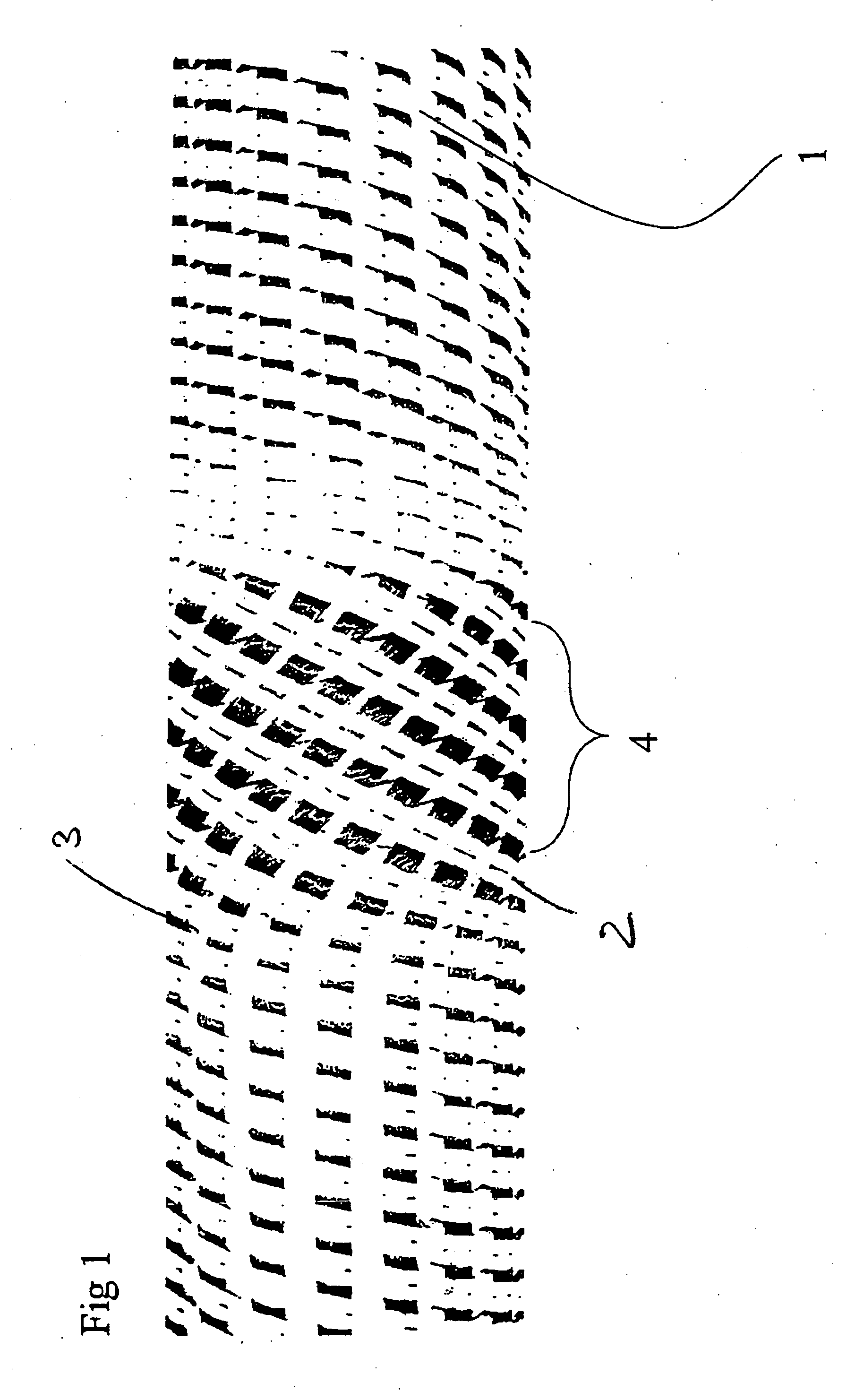
[0020]In the variant according to the invention, which is shown in FIG. 1, the standing ends 3 made of carbon fibers extending along a base body 1 are deflected twice with respect to their direction in a region 4 and thus form a weak point in the structure, which is used for targeted force input, in other words, by means of which, on the one hand, the load peak which initiates the deformation process is limited and moreover a targeted triggering is favoured, which is used for continuously high energy absorption during he deformation process. The production of this region with a deviating depositing angle of the standing ends 3 takes place by means of a rotary movement of a base body 1 taking place in addition to the feed movement of the base body 1 over a predeterminable angle.

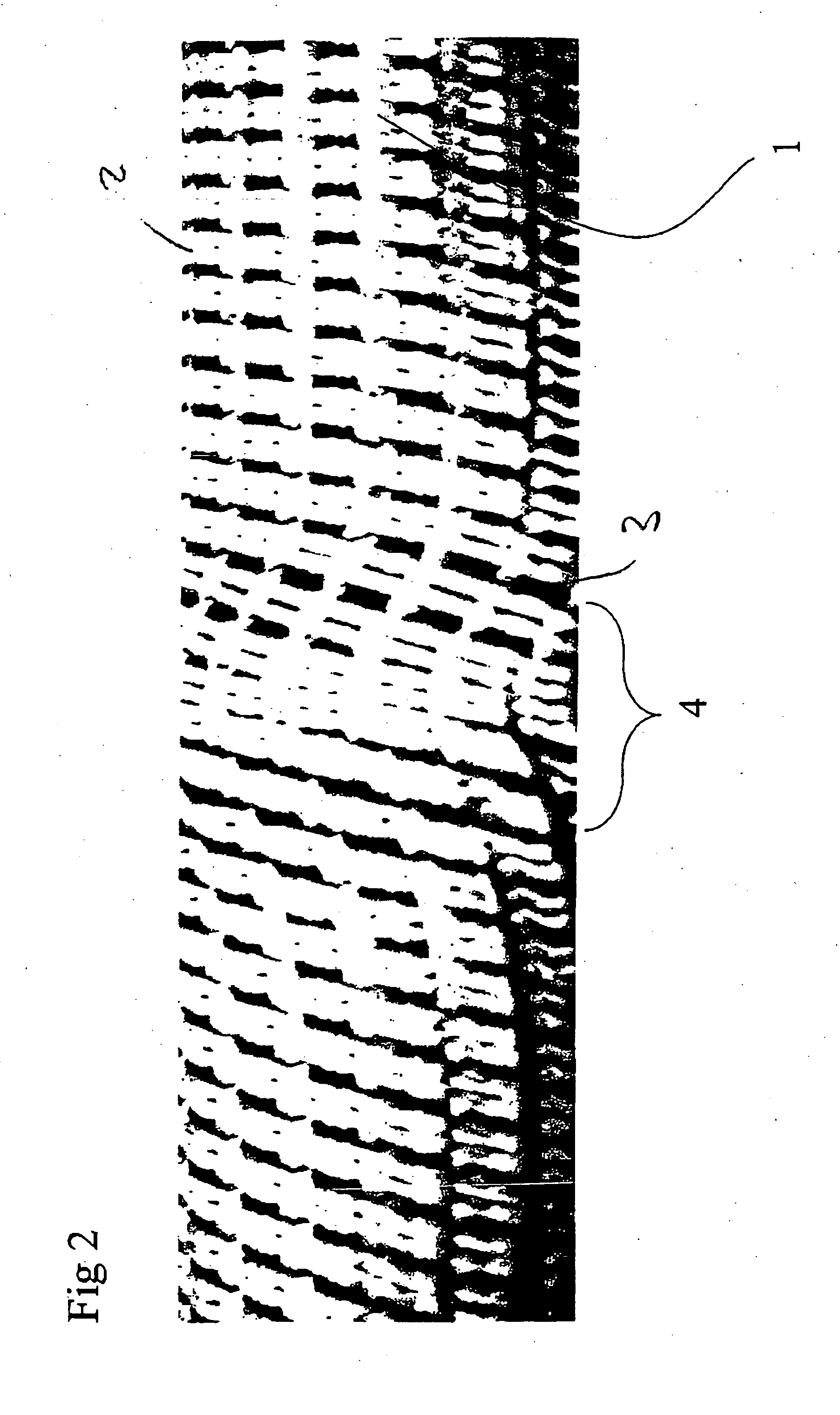
[0021]In the example of FIG. 2, the rotary process of the base body 1 takes place back and forth over a predeterminable angle. As a result, the standing ends run at the same height on both sides of the region ...


PUM

PropertyMeasurementUnit
Angleaaaaaaaaaa
Tensile propertiesaaaaaaaaaa
Energyaaaaaaaaaa

Abstract

Energy-absorbing textile structure, in particular for use in vehicle construction, which has high-tensile yarns for absorbing force, is formed by a braided fabric (2) with standing ends (3) in the force input direction and in that the textile structure has at least one region (4) with local modification of the fiber structure (2, 3).

Description

CROSS REFERENCE TO RELATED APPLICATIONS[0001]This application claims the benefit of German patent application no. 10 2006 004 885.7, filed Feb. 3, 2006, herein incorporated by reference.BACKGROUND OF THE INVENTION[0002]The invention relates to an energy-absorbing textile structure, in particular for use in vehicle construction, which has high-tensile yarns for absorbing force, and a method for producing the textile structure.[0003]Energy-absorbing structures are currently substantially formed by metallic structures, which absorb energy by plastic deformation. However, these metallic structures have the drawback of a high weight in relation to the energy absorption. For this reason, there has already been a change to replacing the metallic structures by textile structures, which contain high-tensile fiber materials. These have high weight-specific energy absorption.[0004]The energy-absorbing structures made of high-tensile textile materials are, however, not plastically deformed like...

Claims


Application Information

Patent Timeline
IPC IPC(8): B32B3/00B29C70/08
CPCD04C1/06Y10T428/1369Y10T428/24636F16F7/006D10B2403/02411Y10T442/3187
Inventor KUMPERS, FRANZ-JURGENRUGER, OLAFPFITZER, HANNO
Owner SGL KUMPERS GMBH & CO KG
Why Eureka
Try Eureka