
Production line and method for the production of cast parts, from a metallic melt, in particular a light molten metal, which takes place in a continuous cycle

a production line and metallic melt technology, which is applied in the direction of moulding machine components, mould handling equipment, foundry moulding apparatus, etc., can solve the problems of large quantity of sand and long conveying distances, loss of availability, and increased technical expenditure caused by a number of machines and tools for core production, etc., to achieve high loading capacity, economic and flexible, and complex form

Inactive Publication Date: 2009-09-15
HYDRO ALUMINUM ALUCAST
View PDF7 Cites 10 Cited by
  • Summary
  • Abstract
  • Description
  • Claims
  • Application Information

AI Technical Summary

Benefits of technology

[0016]Starting from the above described prior art there was therefore a requirement to provide a production line and a method for producing cast parts from light metal, in particular aluminium-based alloys, which allow economical and flexible production of cast parts, in particular motor units, with a high loading capacity and with a complex form.

Problems solved by technology

Large quantities of sand and long conveying distances are required owing to the protracted thermal process.
Known production lines of the above described type allow motor units to be produced cost effectively in large numbers but are confronted by operating drawbacks which are particularly noticeable if smaller numbers are to be produced or the models of the parts to be cast frequently change.
Thus greater technical expenditure caused by a number of machines and tools is required for core production.
During a tool change, which becomes necessary following a change of model, the large number of complex machine units and the compulsion to run cycle times of less than 60 seconds entails long set-up times and complex assembly work which, in turn, cause availability losses.
These losses induce low flexibility in the known production line as high set-up costs and, in the case of new products, additional investment costs stand in the way of quick adaptation to changed operating conditions or model types.
The use of cores bound with organic binders also entails the problem that the tools used for producing the cores have to be cleaned outside of the core shop at regular intervals.
These gases also lead to corresponding stresses on personnel.
Casting defects can occur during the casting process as a result of gassing cold box cores.
A further drawback of the known production lines that entails high operating costs resides in the necessity of using a furnace with long treatment times for heat treatment and fettling, the furnace providing such high temperatures that the binder of the casting moulds is broken down and solution treatment is carried out at the same time.
The flexibility with respect to a variation in the heat treatment parameters is severely limited by coupling to the thermal desanding.
The purely thermal desanding proves to be a problem in the case of sand adhesions (penetration, organic condensates), in particular in the inner channels of a motor unit.
High expenditure for the sand circulation owing to high sand temperatures, large quantities of sand, the necessity of cooling the sand to a defined temperature and the very high space requirement for the furnace additionally contribute to the fact that the known production lines may only be operated economically if the same motor units are produced in high numbers over a long production cycle.

Method used


Image

  • Production line and method for the production of cast parts, from a metallic melt, in particular a light molten metal, which takes place in a continuous cycle
  • Production line and method for the production of cast parts, from a metallic melt, in particular a light molten metal, which takes place in a continuous cycle

Examples


Embodiment Construction

[0067]The invention will be described in more detail hereinafter with reference to an embodiment.

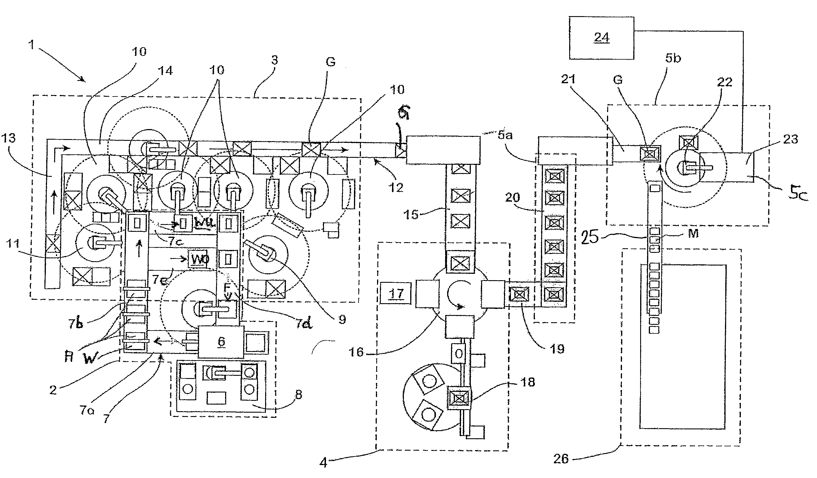
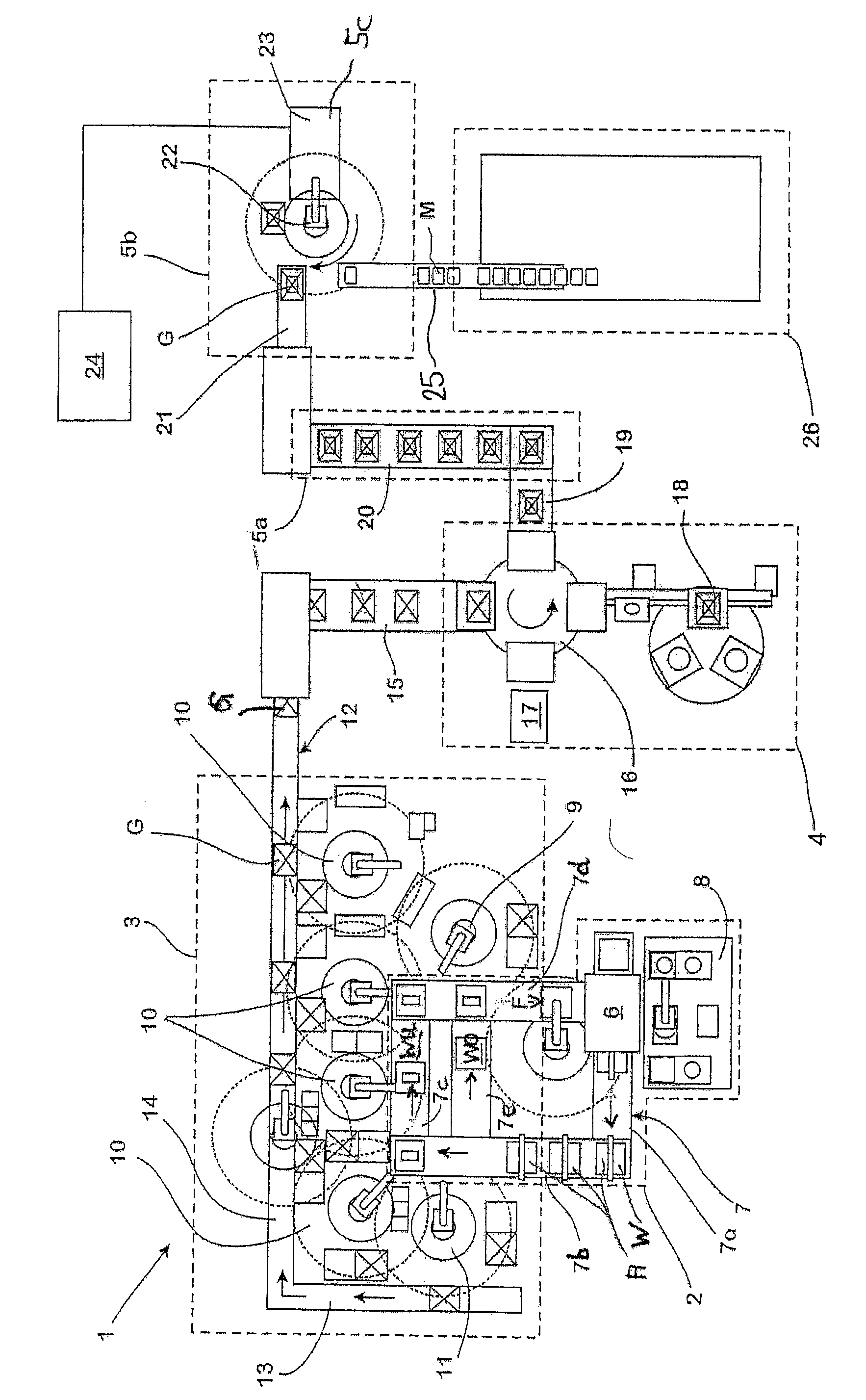
[0068]The single FIGURE schematically and in plan view shows a production line 1 for fully automated production of motor units made of an aluminium alloy. The production line comprises a core production unit 2 for producing casting cores, a mould assembly unit 3 for assembling casting moulds G formed as core packages, a casting unit 4 for filling aluminium melt into the casting moulds G, a cooling unit 5a for solidifying the molten metal contained in the casting mould G and a demoulding unit 5b for destructive removal of the respective casting mould G and a quenching unit 5c of the cast part M.

[0069]The core production unit 2 comprises a core shooting station 6 and a transporting device 7 constructed as a conveyor section. The transporting device 7 is divided into four sections 7a, 7b, 7c and 7d which are arranged at a right angle to each other such that, in plan view, they form the side...


PUM

PropertyMeasurementUnit
cycle timeaaaaaaaaaa
timeaaaaaaaaaa
cohesionaaaaaaaaaa

Abstract

The invention relates to a production line for the production of cast parts (M) from a metallic melt, in particular a light molten metal, which takes place in a continuous cycle, comprising a plurality of functional units, including a core production unit (2) for the production of casting cores, a mould assembly unit (3) for assembling casting moulds (G) formed as core packages, a casting unit for filling the molten metal into the casting moulds (G), a cooling unit (5a) for cooling the molten metal respectively contained in the casting moulds (G), and a demoulding unit (5b) for destructive removal of the casting mould (G) from the cast part (M). A production line of this type allows economical and flexible production of cast parts, in particular motor units, with a high loading capacity and complex form according to the invention in that the functional units (2 to 5b) successively passed through in each case are directly connected to each other by a respective conveying device (12, 19), and in that the cycle time with which the production line (1) ejects finished cast parts (M) is determined by the cycle time with which the core production unit (2) supplies the casting cores produced by the core production unit.

Description

CROSS-REFERENCE TO RELATED APPLICATIONS[0001]This application is a National Phase Application of International Application No. PCT / EP2004 / 14388, filed on Dec. 17, 2004, which claims the benefit of and priority to German patent application no. DE 103 60 694.7, filed on Dec. 19, 2003. The disclosure of each of the above applications is incorporated herein by reference in their entirety.FIELD OF THE INVENTION[0002]The invention relates to a production line for the production of cast parts from a metallic melt, in particular a light molten metal, which takes place in a continuous cycle, comprising a plurality of functional units, including a core shooting and hardening unit for producing casting cores, a mould assembly unit for assembling casting moulds formed as core packages, a casting unit for filling the molten metal into the casting moulds, a cooling unit for solidifying the molten metal contained in the casting mould, a cooling unit for quenching in the context of a heat treatment...

Claims


Application Information

Patent Timeline
Patent Type & Authority Patents(United States)
IPC IPC(8): B22C9/02B22C25/00B22C9/10B22D46/00B22D33/00B22D47/00B22D47/02
CPCB22D47/02
Inventor SMETAN, HERBERT
Owner HYDRO ALUMINUM ALUCAST
Learn More