
Hydrogen fuel cell with integrated reformer

a fuel cell and reformer technology, applied in the field of hydrogen fuel cells, can solve the problems of incompatibility with high concentrations of methanol, inability to use hydrogen gas, and inability to meet the requirements of a dmfc,

Inactive Publication Date: 2009-02-05
OHKAWA TIHIRO
View PDF8 Cites 9 Cited by
  • Summary
  • Abstract
  • Description
  • Claims
  • Application Information

AI Technical Summary

Problems solved by technology

Hydrogen gas, however, is not a convenient fuel for mobile or portable power sources.
Electrolytes, however, such as PEM that is typically used for a DMFC, are generally incompatible with high concentrations of methanol.
Thus, in order to protect the PEM, there is a practical limitation on the concentration of reactant (e.g. methanol) that can be used.
The separated configuration for the fuel cell and reformer of such a system, however, is cumbersome and somewhat impractical.

Method used


Image

  • Hydrogen fuel cell with integrated reformer
  • Hydrogen fuel cell with integrated reformer

Examples


Embodiment Construction

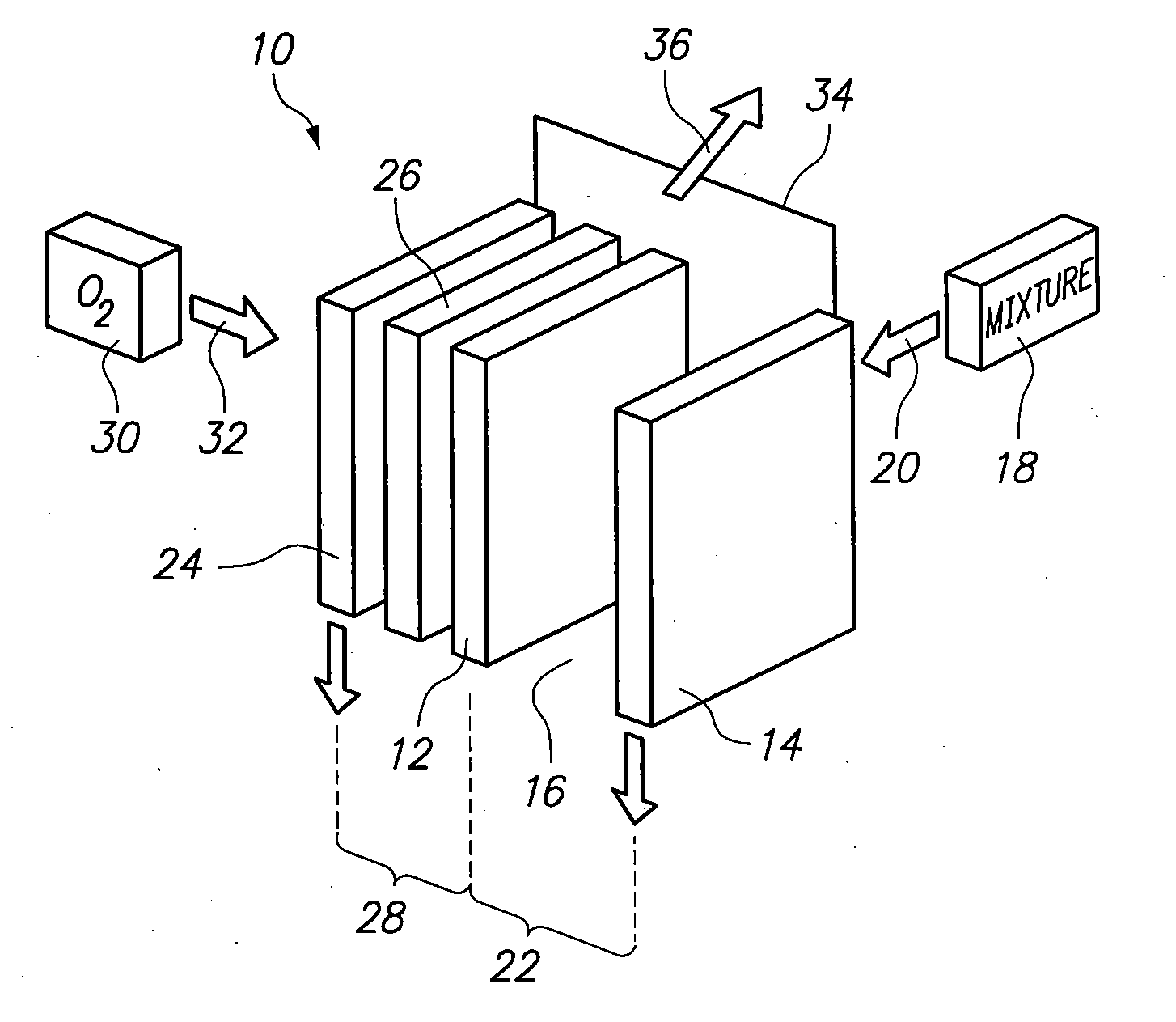
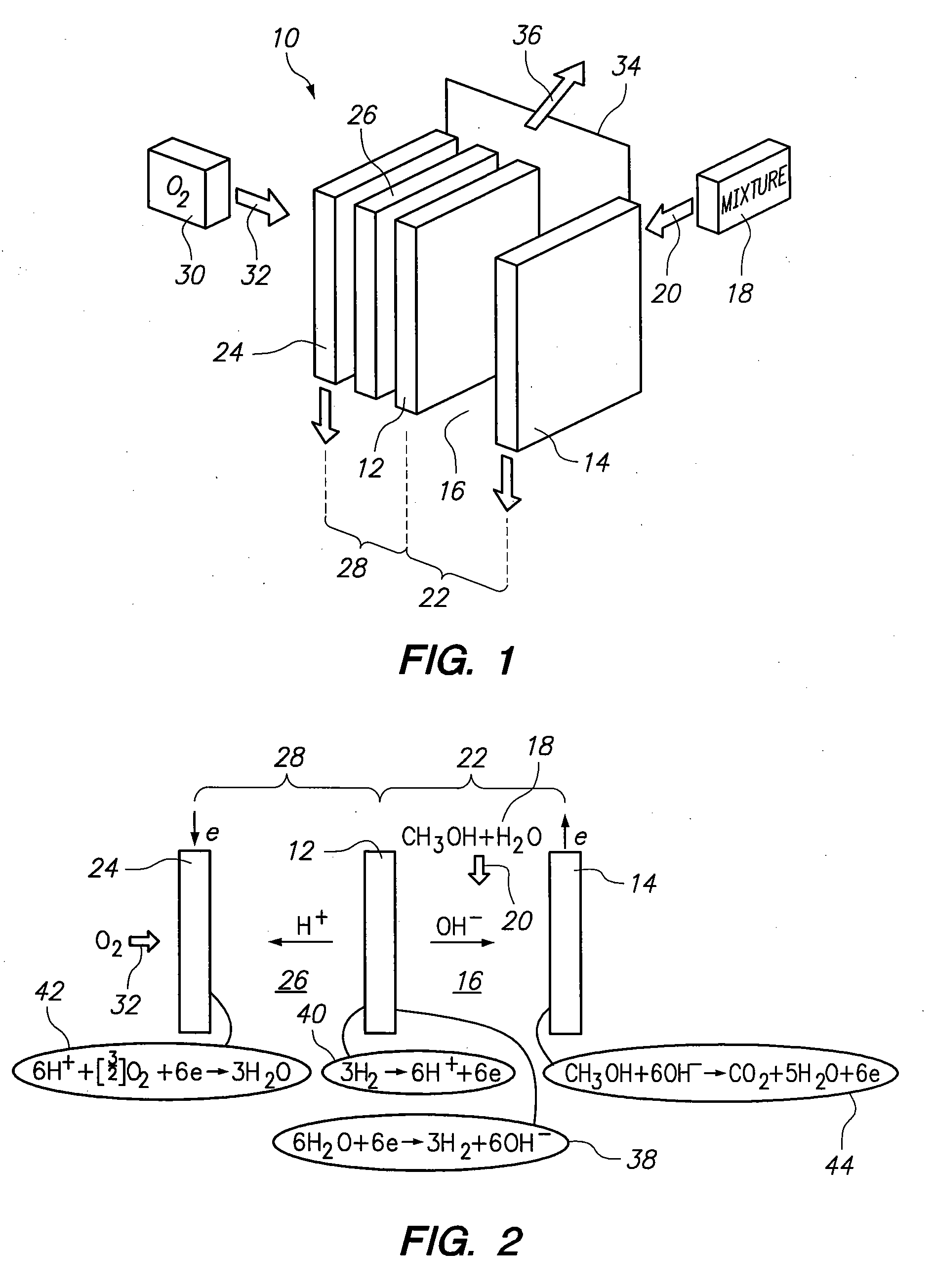
[0017]Referring initially to FIG. 1, a power unit in accordance with the present invention is shown and is generally designated 10. As shown, the power unit 10 includes a mid-electrode 12 and an anode 14, with a gap 16 established therebetween. In this combination, the mid-electrode 12 acts as a cathode for an assisted electrolysis cell 22. FIG. 1 also shows that a source is provided to direct a liquid mixture 18 into the gap 16, as indicated by the arrow 20. Together, the mid-electrode 12 and the anode 14, along with the mixture 18, create the assisted electrolysis cell 22. Preferably, the mixture 18 that is used for the present invention is either methanol and water, or ethanol and water. It will be appreciated, however, that other carbon compounds may be used for the present invention. Further, it is important that the mid-electrode 12 be made of a hydrophobic, porous material, such as a porous carbon. Additionally, the anode 14 of the assisted electrolysis cell 22 can be coated ...


PUM

PropertyMeasurementUnit
electrical currentaaaaaaaaaa
hydrophobicaaaaaaaaaa
alkalineaaaaaaaaaa

Abstract

A unit for generating an electrical current includes an electrolysis cell and a hydrogen fuel cell having a common mid-electrode. This mid-electrode is hydrophobic and separates a PEM electrolyte in the fuel cell from an electrolyte mixture of water and a carbon compound in the electrolysis cell. Electrolysis of the water produces hydrogen at the mid-electrode and carbon dioxide at the anode of the unit. The hydrogen diffuses into the hydrogen fuel cell through the mid-electrode but it prevents the water mixture in the electrolysis cell from contacting the PEM electrolyte in the fuel cell. Oxygen is provided to react with hydrogen protons at the cathode of the fuel cell to produce water. An external circuit is provided between the respective unit anode at the electrolysis cell and the unit cathode at the fuel cell for carrying the electrical current generated by the unit.

Description

FIELD OF THE INVENTION[0001]The present invention pertains generally to fuel cells. More particularly, the present invention pertains to hydrogen fuel cells that are assisted by a reforming unit. The present invention is particularly, but not exclusively, useful as an integrated unit wherein an electrolysis cell is structurally integrated, directly with a hydrogen fuel cell for generating electricity.BACKGROUND OF THE INVENTION[0002]The basic operation of a hydrogen fuel cell is well known. Specifically, in a hydrogen fuel cell, hydrogen is directed to the anode on one side of the cell, while oxygen is directed to the cathode on the other side of the cell. At the anode, the hydrogen is split into hydrogen ions (protons) and electrons. An electrolyte, such as a Proton Exchange Membrane (PEM) allows only the protons to pass through the electrolyte to the cathode. Consequently, the electrons are directed along an external circuit to the cathode, creating an electrical current. At the c...

Claims


Application Information

Patent Timeline
Patent Type & Authority Applications(United States)
IPC IPC(8): H01M8/06
CPCH01M4/8615H01M8/0618H01M8/083H01M8/1011Y02E60/522H01M8/186Y02E60/523Y02E60/528H01M8/1013Y02E60/50
Inventor OHKAWA, TIHIRO
Owner OHKAWA TIHIRO
Learn More