
Outer Sidewall Retention Scheme For A Singlet First Stage Nozzle

a technology of retention scheme and retaining ring, which is applied in the direction of machines/engines, stators, liquid fuel engines, etc., can solve the problems of high pressure loading of nozzles, cracks in airfoil trailing edges, and reduced static pressure between inlet and outlet planes, so as to improve thermal isolation of retaining rings and reduce costs. , the effect of improving sealing

Inactive Publication Date: 2009-02-12
GENERAL ELECTRIC CO
View PDF8 Cites 22 Cited by
  • Summary
  • Abstract
  • Description
  • Claims
  • Application Information

AI Technical Summary

Benefits of technology

[0026]The following embodiments of the present invention have many advantages, including improved nozzle stability, determinate nozzle loading, airfoil trailing edge stress reduction, improved retaining ring thermal isolation, improved nozzle arrangement assembly flexibility, improved chordal hinge sealing, and improved nozzle castibility.

Problems solved by technology

The directing process performed by the nozzles also accelerates gas flow resulting in a static pressure reduction between inlet and outlet planes and high pressure loading of the nozzles.
Such stressing of the airfoils may lead to formation of cracks in the airfoil trailing edge.
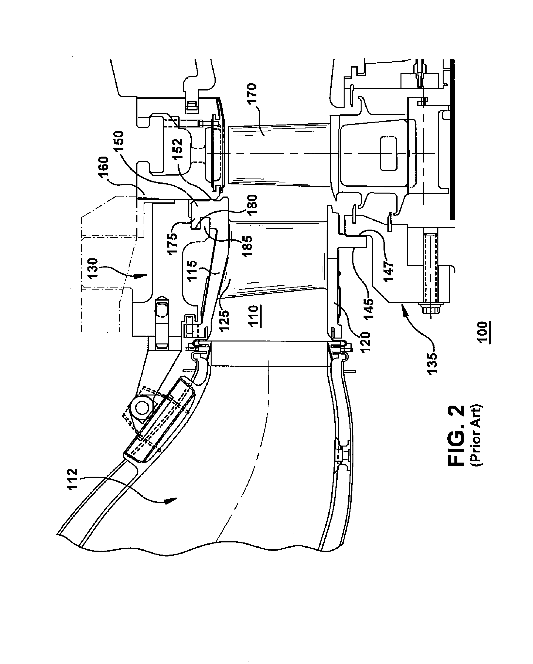
This change resulted in more determinate nozzle loading and better nozzle sealing but also resulted in less than optimal thermal isolation of the retaining ring and thereby a substantial cost increase to the nozzle arrangement.
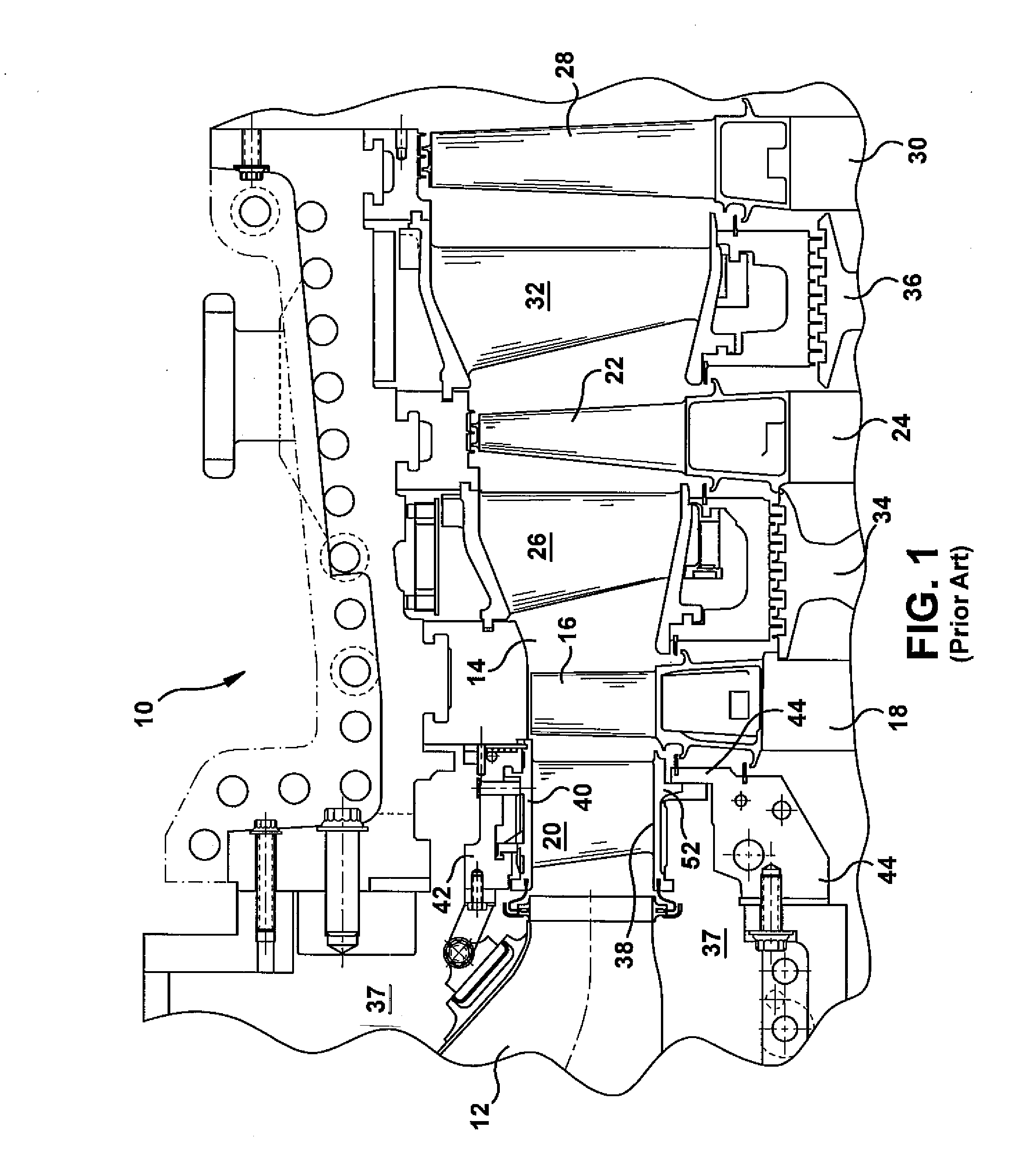
Some of the field issues related to hook retention designs include incomplete chordal hinge sealing, retaining ring out of roundness, and high trailing edge stresses.

Method used


Image

  • Outer Sidewall Retention Scheme For A Singlet First Stage Nozzle
  • Outer Sidewall Retention Scheme For A Singlet First Stage Nozzle
  • Outer Sidewall Retention Scheme For A Singlet First Stage Nozzle

Examples


Embodiment Construction

[0026]The following embodiments of the present invention have many advantages, including improved nozzle stability, determinate nozzle loading, airfoil trailing edge stress reduction, improved retaining ring thermal isolation, improved nozzle arrangement assembly flexibility, improved chordal hinge sealing, and improved nozzle castibility.

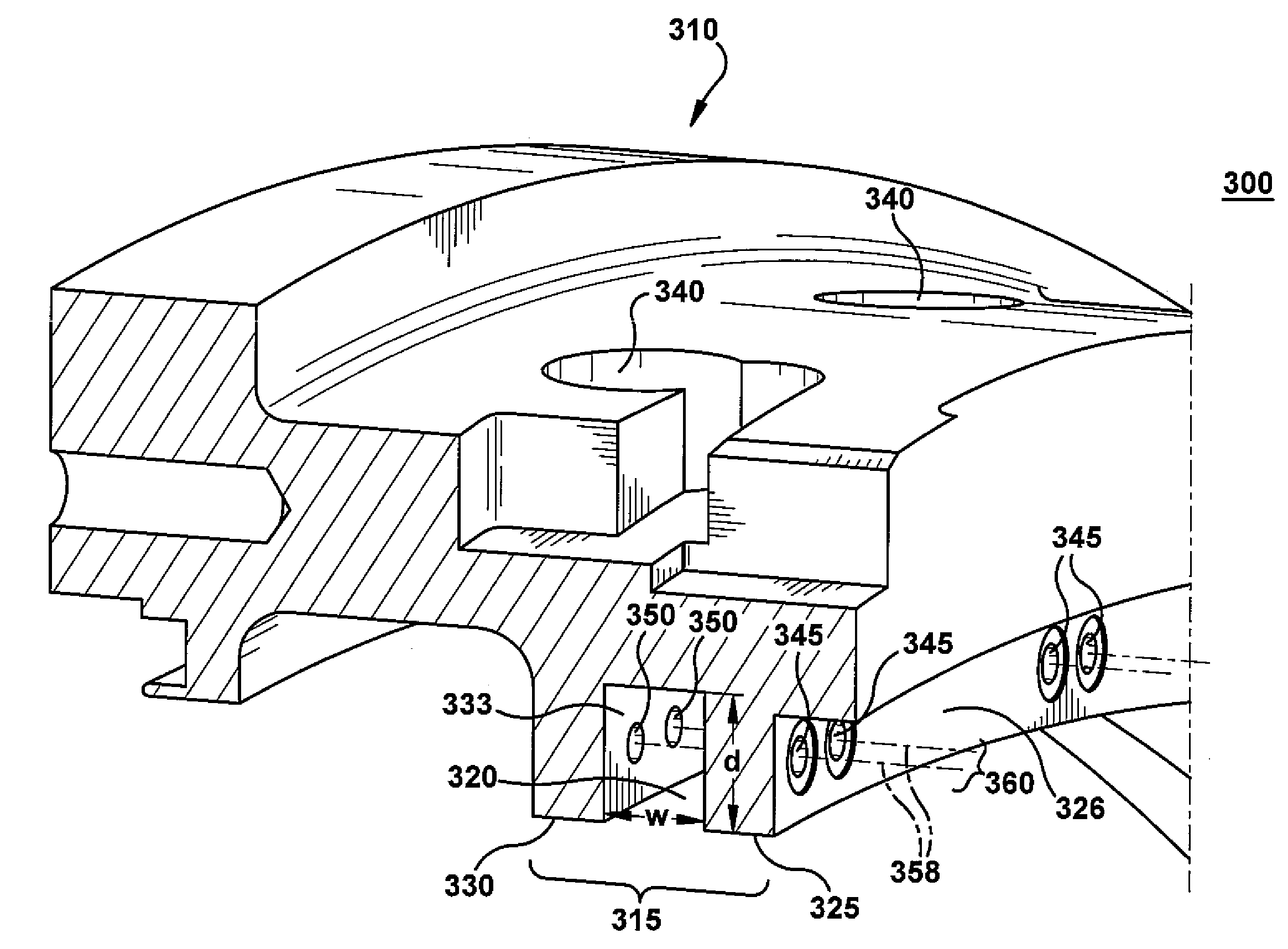
[0027]Power generation gas turbines traditionally use a hook retention scheme. Hook retention schemes inherently have several design drawbacks that cannot be overcome. The present invention overcomes the drawbacks of the hook design. An embodiment of the inventive design retains the first stage nozzle with two axially oriented pins. The benefits of this retention scheme include improved nozzle stability, determinate nozzle loading, airfoil trailing edge stress reduction, improved retaining ring thermal isolation, improved nozzle arrangement assembly flexibility, improved chordal hinge sealing, and improved nozzle castibility.

[0028]More specifically...


PUM


Abstract

An outer sidewall retention scheme for a singlet first stage nozzle of a gas turbine. The retention scheme includes a circumferential retaining ring with a main body and a pair of circumferential retaining lands projecting inward radially. A circumferential annular retaining groove is formed between the pair of circumferential retaining lands. A first lug and a second lug mounted on an outer face of the outer sidewall of each nozzle are adapted to fit within the circumferential annular retaining groove of the retaining ring and are supported radially and circumferentially by a first retaining pin and a second retaining pin, each pin passing though the circumferential retaining lands. Each nozzle further includes a chordal hinge rail and seal on the outer sidewall and a chordal hinge rail and seal on the inner sidewall providing axial support for the nozzle.

Description

BACKGROUND OF THE INVENTION[0001]The invention relates generally to an arrangement for mounting gas turbine nozzles and more specifically to an outer sidewall retention scheme for a singlet first stage nozzle.[0002]In a gas turbine, hot gases of combustion flow from combustors through first-stage nozzles and buckets and through the nozzles and buckets of follow-on turbine stages. The first-stage nozzles typically include an annular array or assemblage of cast nozzle segments each containing one or more nozzle stator vanes per segment. Each first-stage nozzle segment also includes inner and outer sidewall portions spaced radially from one another. Upon assembly of the nozzle segments, the stator vanes are circumferentially spaced from one another to form an annular array thereof between annular inner and outer sidewalls. A nozzle retaining ring coupled to the outer sidewall of the first-stage nozzles supports the first-stage nozzles in the gas flow path of the turbine. An annular noz...

Claims


Application Information

Patent Timeline
Patent Type & Authority Applications(United States)
IPC IPC(8): F02C1/00
CPCF01D9/042F01D9/041
Inventor SNOOK, DANIEL D.BENJAMIN, EDWARD D.HARTER, ARIEL K.HUMANCHUK, DAVID J.
Owner GENERAL ELECTRIC CO
Learn More