Electromagnetic Flow Control, Methods and Uses

a flow control and electromagnetic technology, applied in the field of electromagnetic flow control, can solve the problems of high surface loading, high heating and flow unsteadiness, adverse effects of high-speed flight, etc., and achieve the effect of low power

Inactive Publication Date: 2009-02-12
BOARD OF RGT THE UNIV OF TEXAS SYST
View PDF4 Cites 18 Cited by
  • Summary
  • Abstract
  • Description
  • Claims
  • Application Information

AI Technical Summary

Benefits of technology

[0004]One or more problems associated with current limitations in aerodynamic actuation are solved as described herein. Such improvements include an actuator for controlling surfaces that is lightweight, compact and requires very low power.

Problems solved by technology

Unfortunately, such methods have adverse consequences for high-speed flight, such as high surface loading, high heating and flow unsteadiness.
The methods have also been found to cause undesirable aerodynamic interference with other vehicular components.

Method used


Image

  • Electromagnetic Flow Control, Methods and Uses
  • Electromagnetic Flow Control, Methods and Uses
  • Electromagnetic Flow Control, Methods and Uses

Examples


Embodiment Construction

[0030]Although making and using various embodiments are discussed in detail below, it should be appreciated that the present invention provides many inventive concepts that may be embodied in a wide variety of contexts. The specific aspects and embodiments discussed herein are merely illustrative of ways to make and use the invention, and do not limit the scope of the invention.

[0031]In the description which follows like parts may be marked throughout the specification and drawing with the same reference numerals, respectively. The drawing figures are not necessarily to scale and certain features may be shown exaggerated in scale or in somewhat generalized or schematic form in the interest of clarity and conciseness.

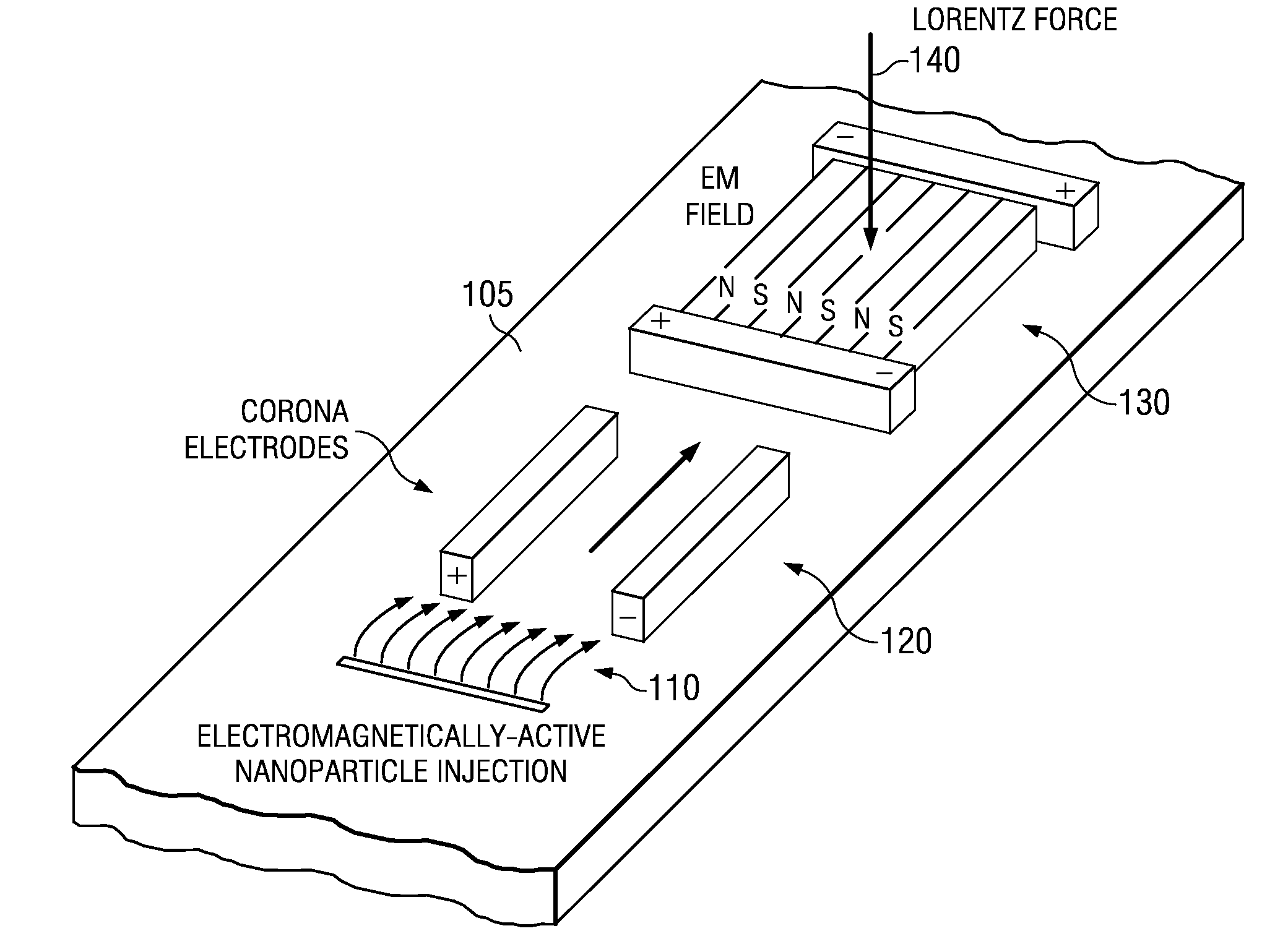
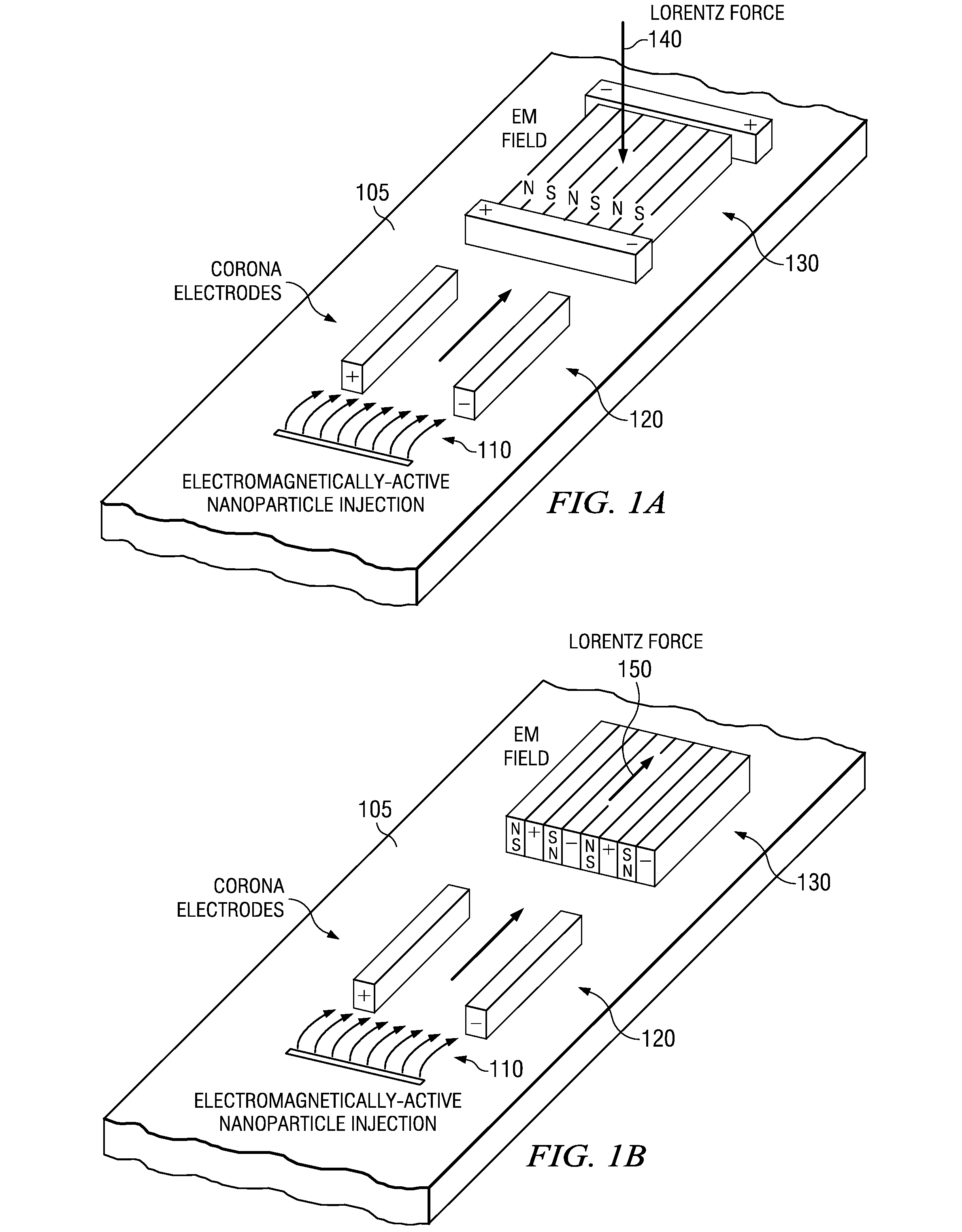
[0032]As described herein, EMFC uses electromagnetic (EM) interactions to manipulate air flow that is ionized by seeding with electromagnetically conducting materials. Control forces and moments typically produced by a traditional flap are provided through a distortion o...


PUM


Abstract

Actuation for control of surfaces is provided through use of a conducting material comprising electrolyte particles electrically charged with electromagnetic fields in boundary layers. Interactions of the electrically charged particles with electromagnetic fields in boundary layers are coordinated for generation of control forces for various applications.

Description

CROSS REFERENCES TO RELATED APPLICATIONS[0001]This application claims the benefit of U.S. Provisional Application No. 60 / 922,768 filed Apr. 10, 2007.BACKGROUND OF THE INVENTION[0002]This relates in general to the field of electromagnetics and, more particularly, to electromagnetic flow control.[0003]Current methods for high-speed aerodynamic surface and vehicle control involve actuation of large, bulky control surfaces or the use of reaction jets. Unfortunately, such methods have adverse consequences for high-speed flight, such as high surface loading, high heating and flow unsteadiness. The methods have also been found to cause undesirable aerodynamic interference with other vehicular components.SUMMARY OF THE INVENTION[0004]One or more problems associated with current limitations in aerodynamic actuation are solved as described herein. Such improvements include an actuator for controlling surfaces that is lightweight, compact and requires very low power.[0005]Actuation is achieved...

Claims


Application Information

Patent Timeline
Patent Type & Authority Applications(United States)
IPC IPC(8): G01F1/64
CPCB64C21/00B64C2230/12Y02T50/166B64C23/005Y02T50/10
Inventor LU, FRANK K.WILSON, DONALD R.DUTTON, J. CRAIG
Owner BOARD OF RGT THE UNIV OF TEXAS SYST
Why Eureka
Try Eureka