Method for wind turbine yaw control

a technology of wind turbines and control methods, applied in the direction of electric generator control, machines/engines, instruments, etc., can solve the problems of retaining the difficulty of sensitivity to tolerances in baseline measurements, the dependence on the accuracy of sensor mounting, and the difficulty of traditional approach

Inactive Publication Date: 2009-02-12
SIEMENS AG
View PDF11 Cites 39 Cited by
  • Summary
  • Abstract
  • Description
  • Claims
  • Application Information

AI Technical Summary

Benefits of technology

[0034]It is also possible that each wind turbine rotor blade is equipped with at least one anemometer for measuring the component of the wind speed in the rotor plane u. This would equalise possible loads which could occur due to an anemometer located at a rotor blade.

Problems solved by technology

However, some difficulties occur in this traditional approach.
Moreover, the flow distortion in the field may be different from the flow distortion in the test turbine, for instance, as a result of differences in nacelle equipment that may affect speed-up characteristics over the nacelle and differences in ambient flow conditions.
This solution solves the issue of flow distortion but it retains the difficulties of sensitivity to tolerances in the baseline measurements and the dependence on the accuracy of sensor mounting.
It is very difficult to achieve an uncertainty in the order of ±5° when all the elements of the uncertainty are taken into account.
Furthermore, the solution of the flow distortion problem is paid in the location of the wind direction sensors in a position that is very difficult to access.
This causes difficulties regarding maintenance and repair.
A further result is a rather complex arrangement of bearings and torque tubes.

Method used


Image

  • Method for wind turbine yaw control
  • Method for wind turbine yaw control
  • Method for wind turbine yaw control

Examples


first embodiment

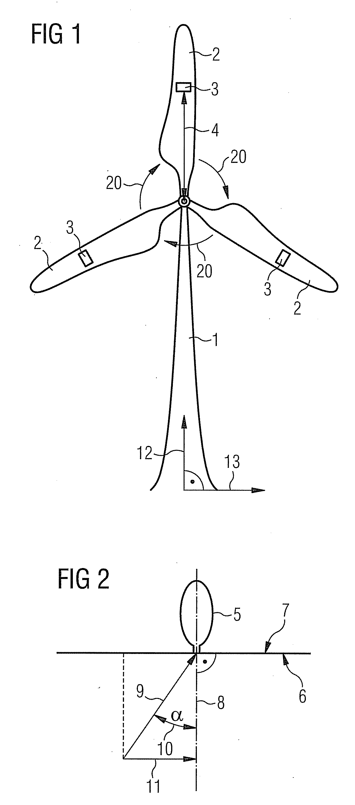
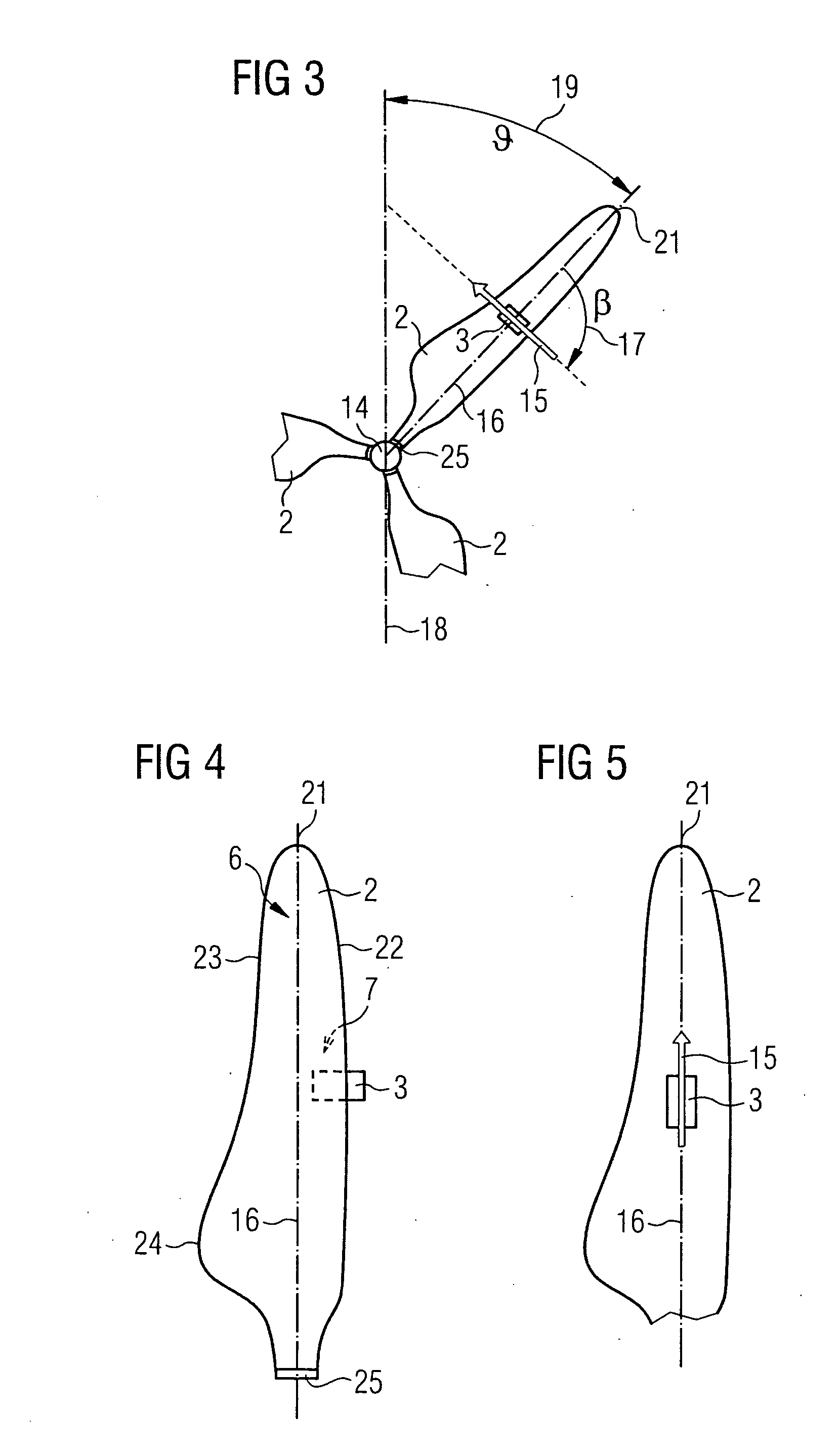
[0041]the inventive method and the inventive wind turbine will now be described in more detail with respect to FIGS. 1 to 4. FIG. 1 schematically shows an inventive wind turbine. The wind turbine comprises a wind turbine tower 1 and a rotor with three rotor blades 2. The rotation of the rotor is indicated by arrows 20. Each rotor blade 2 is equipped with an anemometer 3 which is located at a particular distance 4 from the rotor axis. The anemometers 3 are fixed to the rotor blades 2. Alternatively, only one rotor blade 2 or two rotor blades can be equipped with an anemometer 3. Although the anemometers are shown to be located in the middle of the rotor blades 2 it is actually advantageous to locate them near the root ends of the blades 2 in order to influence the blade's aerodynamics as little as possible. In the figure the vertical direction is indicated by an arrow 12 and the horizontal direction is indicated by an arrow 13.

[0042]FIG. 2 schematically shows how the yaw angle error ...

second embodiment

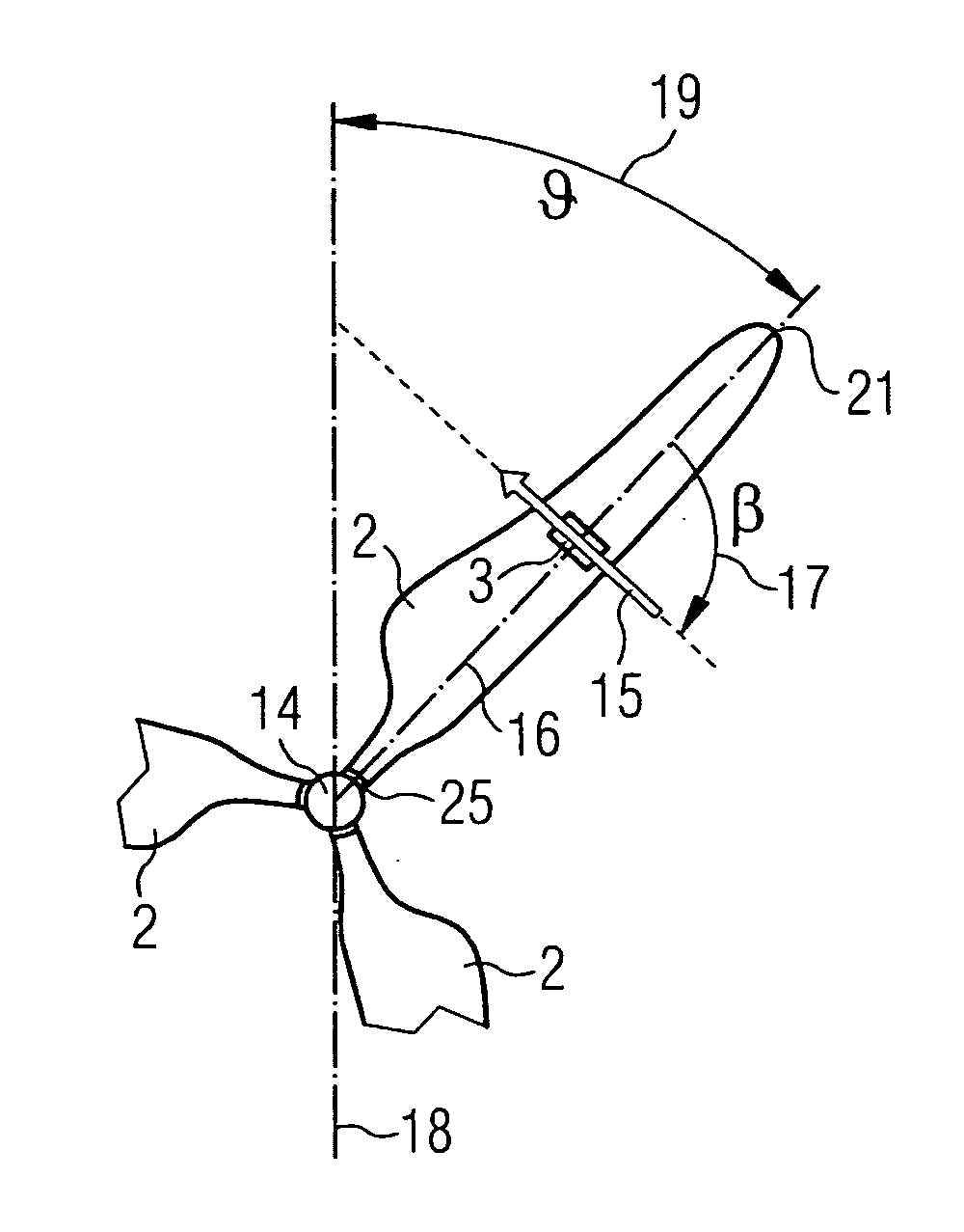
[0057]In the inventive method of yaw control the yaw angle error is explicitly determined by the use of a measurement of the ambient wind speed and a measurement of a wind speed in the rotor plane. An anemometer for measuring the ambient wind speed w, which is indicated by the reference numeral 9, may be located upwind at the rotor axis, at the turbine nacelle 5, at one of the wind turbine rotor blades 2 or at a separate tower in the field. Preferably the ambient wind speed w is measured by at least one of the anemometers 3 which are fixed to the rotor blades 2. In this case the anemometer 3 may be a two- or a three-axis anemometer. The measurement of the ambient wind speed w by at least one anemometer 3 which is located at one of the rotor blades 2 has the advantage that the ambient wind speed w can be measured in nearly undisturbed conditions. Especially turbulence caused by the wind turbine nacelle or turbulence which may occur near the rotor axis are avoided. Generally the anemo...


PUM


Abstract

A method for yaw control for a wind turbine comprising a rotor with a rotor blade, the rotor defining a rotor axis and a rotor plane to which the rotor axis is perpendicular, in which the rotor axis is turned to minimise the yaw angle between the ambient wind direction and the rotor axis is provided, wherein the turning of the rotor axis is performed based on the measurement of a wind speed in the rotor plane at the rotor blade. Furthermore, a wind turbine which comprises a rotor which includes a rotor axis and a rotor plane perpendicular to the rotor axis and an anemometer for measuring the ambient wind speed is provided. The wind turbine further comprises an anemometer which is located such at a rotor blade at a particular distance from the rotor axis as to allow for measuring a wind speed in the rotor plane.

Description

CROSS REFERENCE TO RELATED APPLICATIONS[0001]This application claims priority of European Patent Office application No. 07014330.0 EP filed Jul. 20, 2007, which is incorporated by reference herein in its entirety.FIELD OF INVENTION[0002]The present invention relates to a method for yaw control of a wind turbine.BACKGROUND OF INVENTION[0003]Many wind turbines comprise a rotor with its axis in a horizontal position. Wind turbines with horizontal axis require yawing. The yaw angle error is the angle between the rotor axis and the wind direction. To achieve maximum capacity of the wind turbine the rotor axis should be parallel to the wind direction. This means that the yaw angle error has a value of 0°. In this consideration, a vertical tilt angle many rotor axes have in order to prevent the blades from touching the tower at high wind speeds and which, strictly speaking, means that the rotor axis is actually slightly off the parallel orientation, is neglected.[0004]During the yawing pro...

Claims


Application Information

Patent Timeline
Patent Type & Authority Applications(United States)
IPC IPC(8): H02P9/04
CPCF03D7/0204F03D11/00F05B2270/304F05B2270/32Y02E10/723G01P5/16G01P5/24G01P13/02Y02E10/722G01P5/06Y02E10/72
Inventor STIESDAL, HENRIK
Owner SIEMENS AG
Why Eureka
Try Eureka