
Method and device for determining the length of a shortest path in a network

Inactive Publication Date: 2009-02-12
MAX PLANCK GESELLSCHAFT ZUR FOERDERUNG DER WISSENSCHAFTEN EV
View PDF4 Cites 31 Cited by
  • Summary
  • Abstract
  • Description
  • Claims
  • Application Information

AI Technical Summary

Benefits of technology

[0026]There exist natural applications, where length-only shortest path queries are good enough, and not all the edges along the path are required. Most car navigation systems, for example, have at most a lo

Problems solved by technology

Up to now, no better algorithm is known for computing the shortest path between two given nodes in a graph if no pre-processing is allowed and no assumptions on the graph, except for non-negative edge lengths, are made.
Hence, the problem of determining the length of a shortest path in the network may be divided into the problem of pre-processing the network or creating a data structure from the network such that efficient queries become possible and the problem of efficiently querying that data structure.
However, a naïve approach would involve creating a lookup table for all possible queries concerning a given network.
This would be prohibitive for e.g. the US road network, which has about 24 million nodes and 58 million edges.
The (compared to later work) less competitive running times, both for the pre-processing phase as well as the queries are mostly due to the lack of an efficient compression scheme, which (in particular for the networks induced by higher level edges) improves the processing time considerably.
However, it is not clear how much effort in both time and space is necessary to uncompress those edges.
The presented variant is also inherently bidirectional, so both goal-direction as well as one-to-many queries are not easily added.
However, the space consumption is higher, because every node in the network has to store distances to all landmarks.
However, to pre-compute these perfect signs requires an all-pairs shortest-path computation, which takes quadratic time and would be infeasible already for a small portion of the whole road network, e.g. the road network of California.
In the cited articles, it is shown how to cut down on this pre-processing, by putting up signs to sufficiently large regions of the graph, but pre-computation of those signs is still prohibitive for large networks.

Method used


Image

  • Method and device for determining the length of a shortest path in a network
  • Method and device for determining the length of a shortest path in a network
  • Method and device for determining the length of a shortest path in a network

Examples


Embodiment Construction

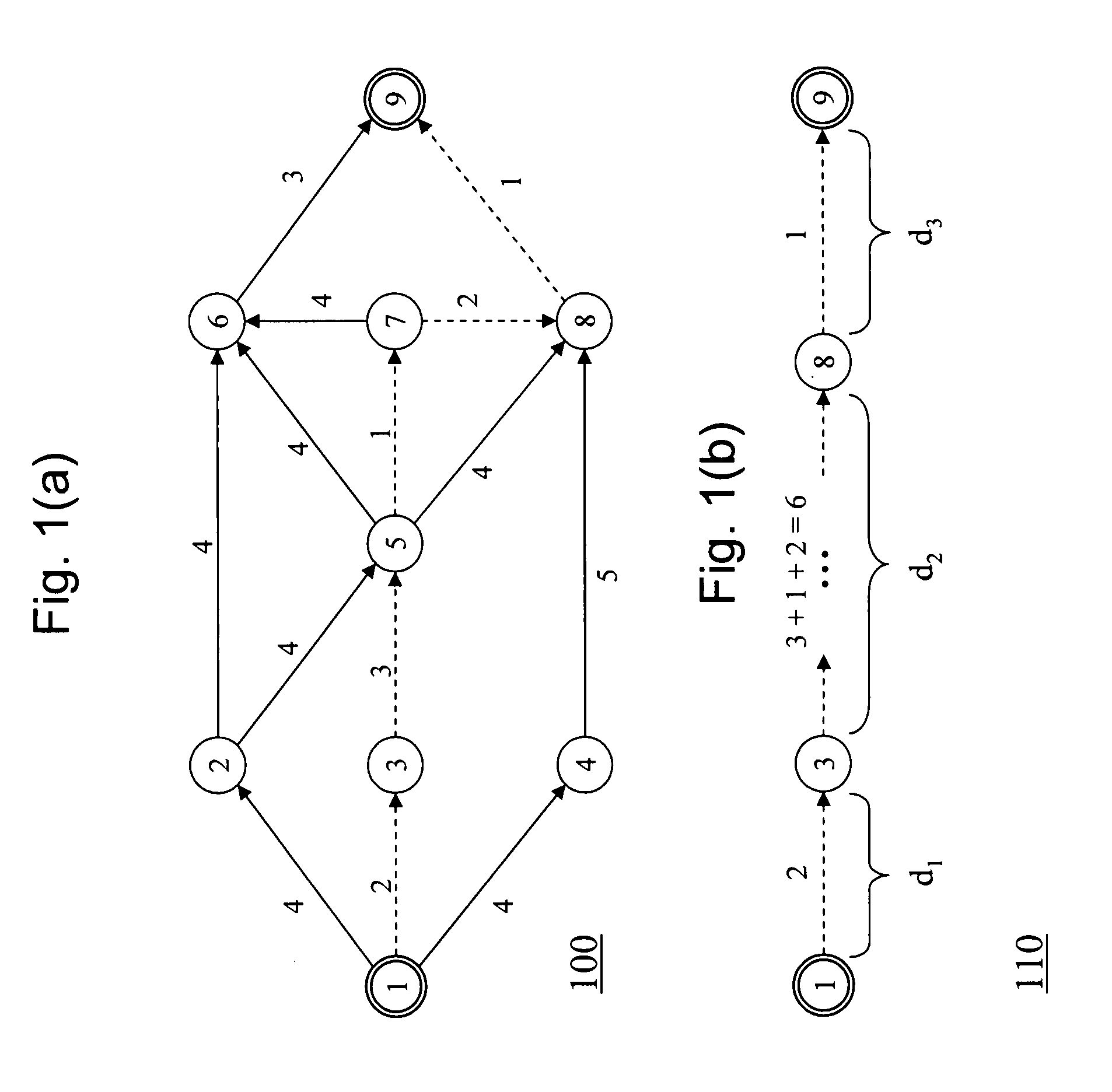
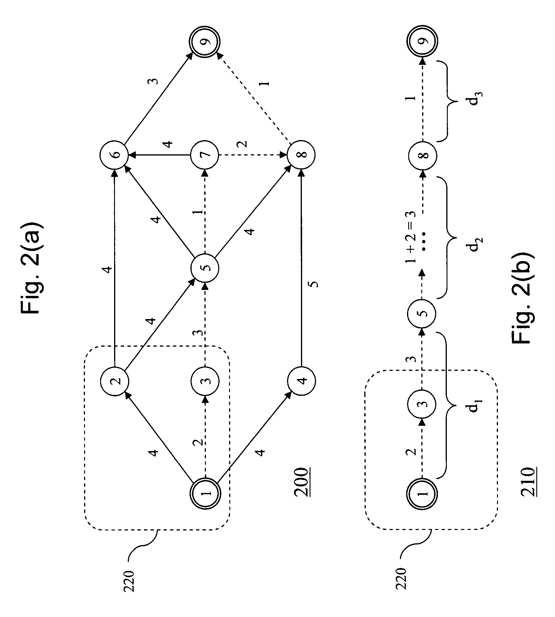
[0037]FIG. 1a shows a schematic representation of a road network 100. The network has nodes 1 through 9, wherein node 1 will be called the source node and node 9 will be called the target node in the following. Each edge in the network is assigned a positive weight, e.g. a distance or travel time.

[0038]The shortest path from source node 1 to target node 9, i.e. the path having minimal combined weight, is indicated by the dotted line and runs through nodes 3, 5, 7 and node 8. The overall length may be obtained by forming the sum of the weights along the shortest path.

[0039]According to the invention, one or several the nodes on the shortest path may now be used for pre-computing and storing information about that shortest path for later use.

[0040]In particular, given the example of FIG. 1a, it may be observed that, knowing the length of the shortest path from the source node 1 to one node, e.g. node 3, and the length of the shortest path from this node, i.e. node 3 in the present exa...


PUM


Abstract

A computer-implemented method for pre-processing a network, wherein the network comprises nodes and edges, each edge having a length measured according to a given metric, comprises the steps of selecting a source and a target node; determining a transit node for the selection; determining a length of a shortest path between the source node and the transit node; and storing it. A method for determining the length of a shortest path in the network may use the pre-processed network to answer the shortest path query in constant time.

Description

BACKGROUND OF THE INVENTION[0001]The present invention relates to a method and a device for determining the length of a shortest path in a network. In particular, the present invention relates to the application of such a method and a device to road networks, for example in a road navigation device.[0002]In general, the shortest path problem is the problem of finding a path between two nodes of a network such that the sum of the weights of its constituent edges is minimized. A practical example is finding the quickest way to get from one location to another on a road map; in this case, the vertices represent locations and the edges represent segments of road and are weighted by the time needed to travel that segment.[0003]Formally, given a weighted graph (that is, a set V of vertices, a set E of edges, and a (real-valued) weight function f: E→R), and one element v of V, find a path P from v to each v′ of V so that∑p∈Pf(p)is minimal among all paths connecting v to v′.[0004]The classi...

Claims


Application Information

Patent Timeline
IPC IPC(8): G08C15/00
CPCG01C21/3446
Inventor BAST, HOLGERFUNKE, STEFANMATIJEVIC, DOMAGOJ
Owner MAX PLANCK GESELLSCHAFT ZUR FOERDERUNG DER WISSENSCHAFTEN EV
Learn More