Cooling system for gantry-mounted components of a computed tomography system

a computed tomography and cooling system technology, applied in tomography, applications, instruments, etc., can solve problems such as hygienic problems

Inactive Publication Date: 2009-02-12
SIEMENS HEALTHCARE GMBH
View PDF13 Cites 23 Cited by
  • Summary
  • Abstract
  • Description
  • Claims
  • Application Information

AI Technical Summary

Benefits of technology

The invention is about a cooling system for a medical examination room that uses compressed air to cool down the components on a gantry. The system has flexible tubes for air feed and discharge, which allows for safe and non-disruptive air flow even if the gantry tilts. The cooling device also has a coupling element that can be connected to a climate control system, so that the air discharge channel doesn't heat up the examination room. The use of compressed air allows for efficient cooling due to the thermodynamic property.

Problems solved by technology

The technical problem addressed in this patent relates to how to effectively cool down the components of a computed tomography apparatus while it operates, including both the X-ray tube and the detector, without compromising their performance and ensuring good image quality. Cooling arrangements tend to struggle with the constant motion of the gantry where these components are located, making traditional methods difficult to implement.

Method used


Image

  • Cooling system for gantry-mounted components of a computed tomography system
  • Cooling system for gantry-mounted components of a computed tomography system
  • Cooling system for gantry-mounted components of a computed tomography system

Examples


Embodiment Construction

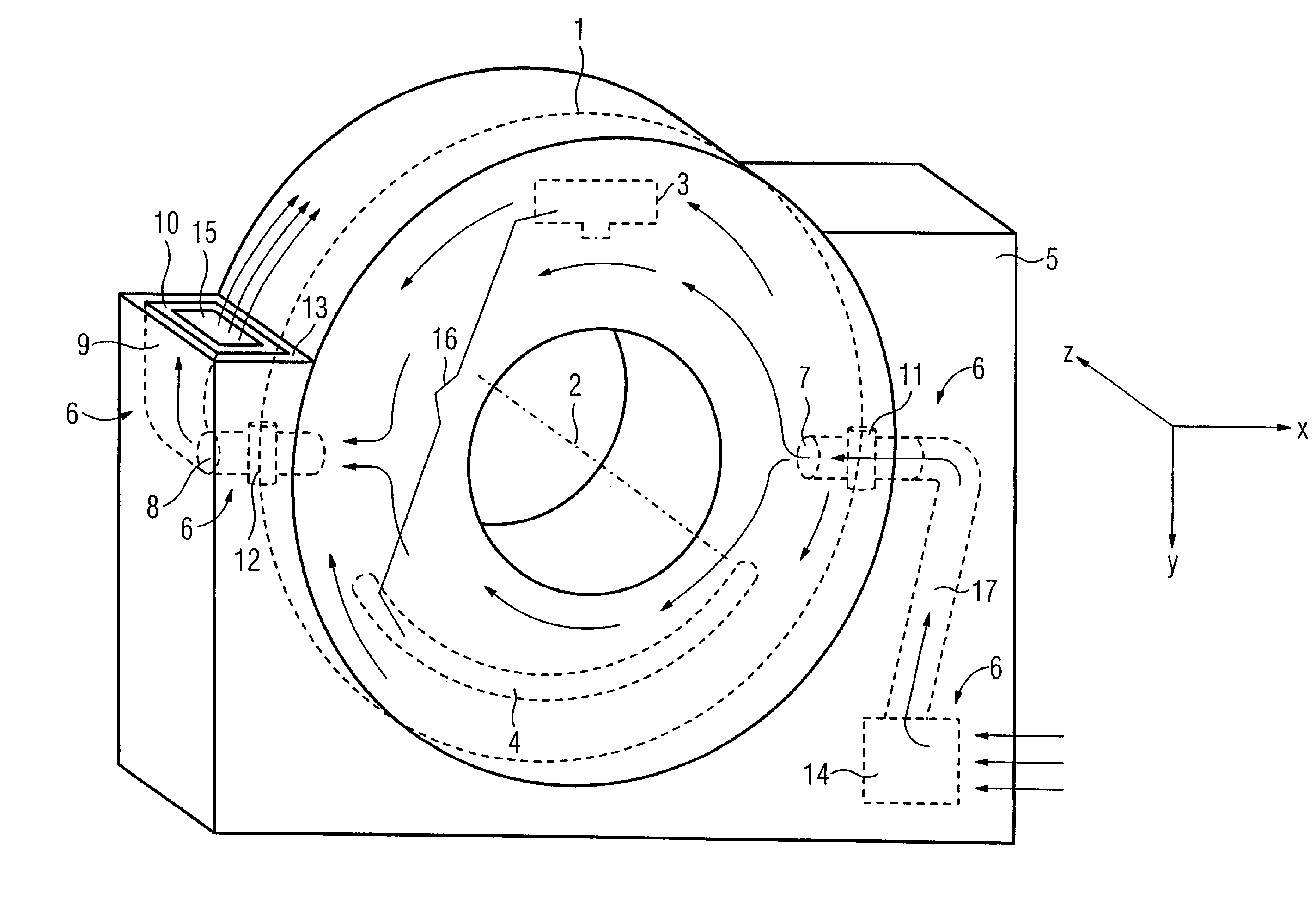
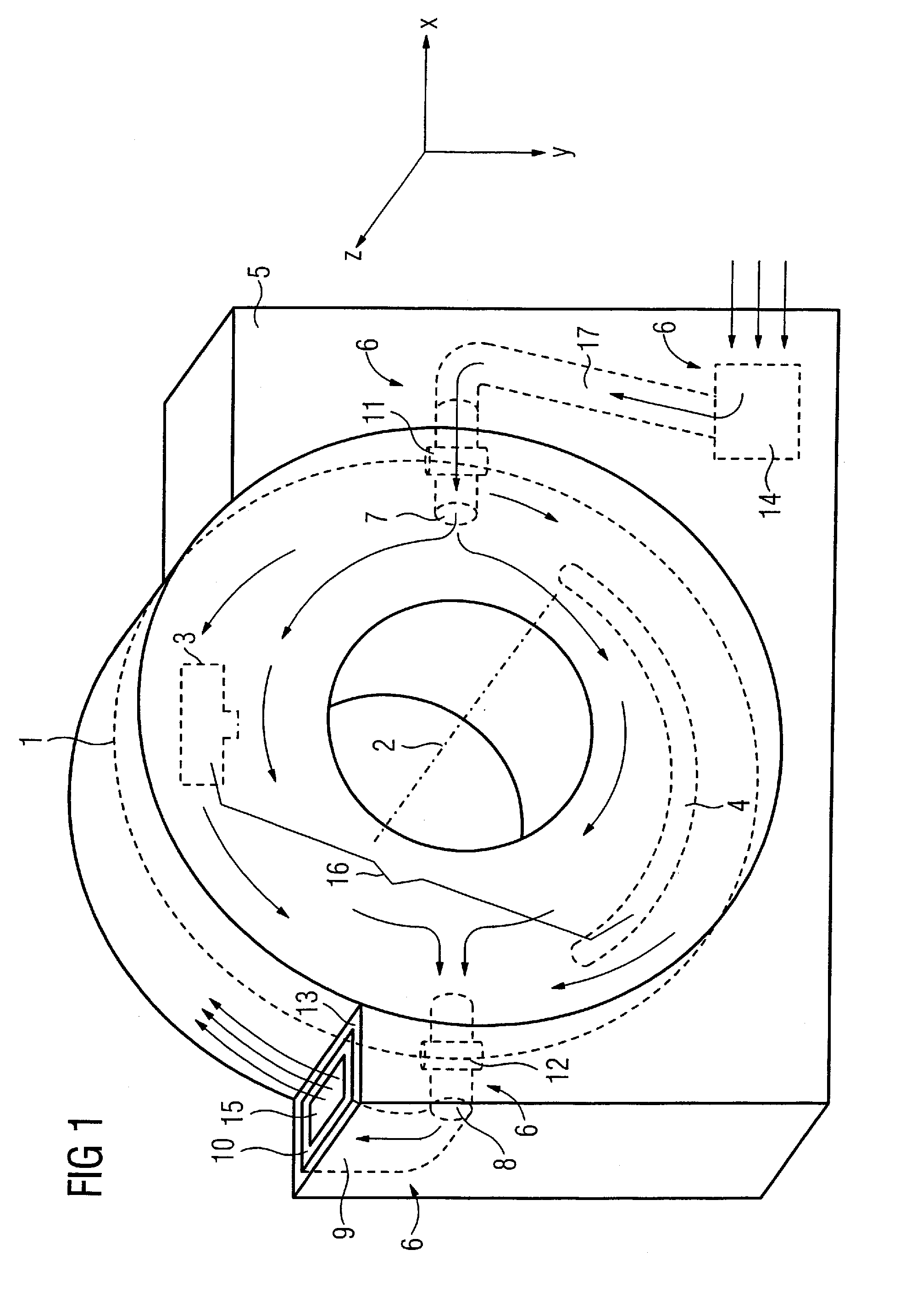
[0025]Located inside the computed tomography apparatus according to the invention that is shown in a perspective view in FIG. 1 is an acquisition system 16, arranged such that it can rotate around a system axis 2 on a gantry 1, for acquisition of projections of an examination region from a number of different projection directions. The acquisition system 16 is essentially formed by two components namely an x-ray tube 3 and a detector 4.

[0026]A patient support device (not shown) with a movable table plate on which a patient can be borne is associated with the computed tomography apparatus. The table plate can be displaced in the direction of the system axis 2 so that an examination region of the patient can be moved through the opening in the housing of the gantry 1 into the measurement region of the acquisition system 16. The patient and the acquisition system 16 can be displaced relative to one another in this manner in the direction of the system axis 2 so that different scanning ...


PUM


Abstract

A computed tomography apparatus has a gantry for mounting components of an acquisition system that are arranged such that they can rotate around a system axis, and a stationary part in which the gantry is supported such that it can tilt. A device for cooling the components by airflow is arranged on the gantry. The cooling device has at least one feed channel and at least one air discharge channel that are arranged between the stationary part and the gantry so that the air current introduced into the gantry via the stationary part is conducted out from the gantry into the stationary part in a directed manner after cooling the components. The direction of the air current directed from the computed tomography apparatus thus does not depend on the tilt of the gantry. Moreover, the computed tomography apparatus is designed such that cooling is achieved with low noise emission since the direct sound propagation path between the exit opening and the gantry is interrupted.

Description


Claims


Application Information

Patent Timeline
Owner SIEMENS HEALTHCARE GMBH
Why Eureka
Try Eureka