Stator joining strip and method of linking adjacent stators

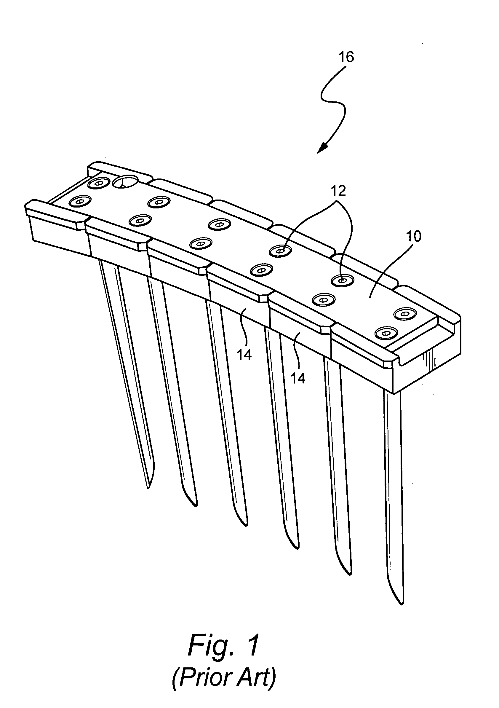
a technology of stators and joining strips, which is applied in the direction of stators, machines/engines, liquid fuel engines, etc., can solve the problems of small pressure fluctuations in the vane, relative motion between the vane and the casing,

Inactive Publication Date: 2009-02-12
GENERAL ELECTRIC CO
View PDF11 Cites 43 Cited by
  • Summary
  • Abstract
  • Description
  • Claims
  • Application Information

AI Technical Summary

Problems solved by technology

In addition, the vanes are subject to small pressure fluctuations during operation.
These result in relative motion between the vane and the casing in which the vanes are assembled.
This causes the hook-fit on the stator base a

Method used


Image

  • Stator joining strip and method of linking adjacent stators
  • Stator joining strip and method of linking adjacent stators
  • Stator joining strip and method of linking adjacent stators

Examples


Embodiment Construction

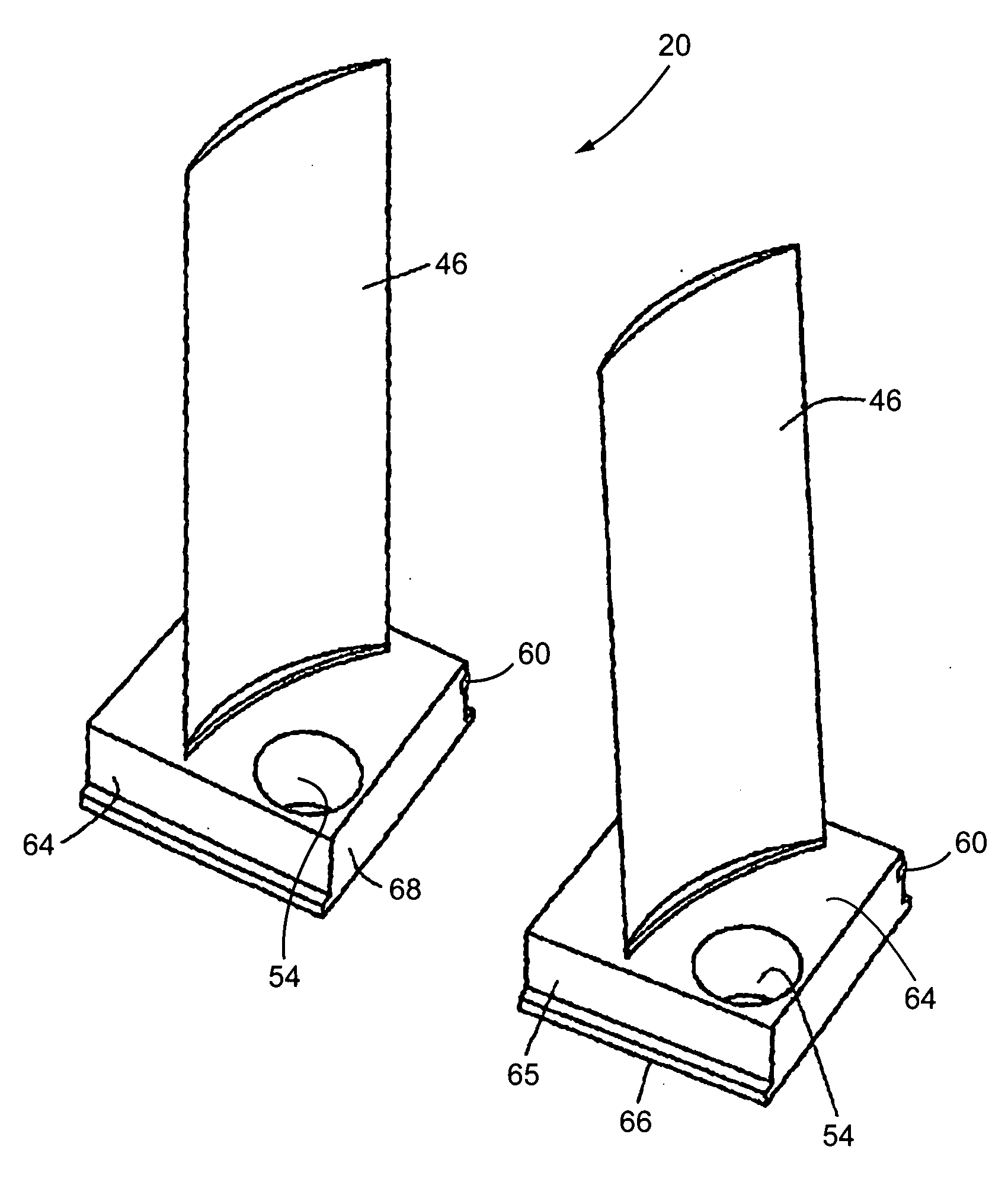
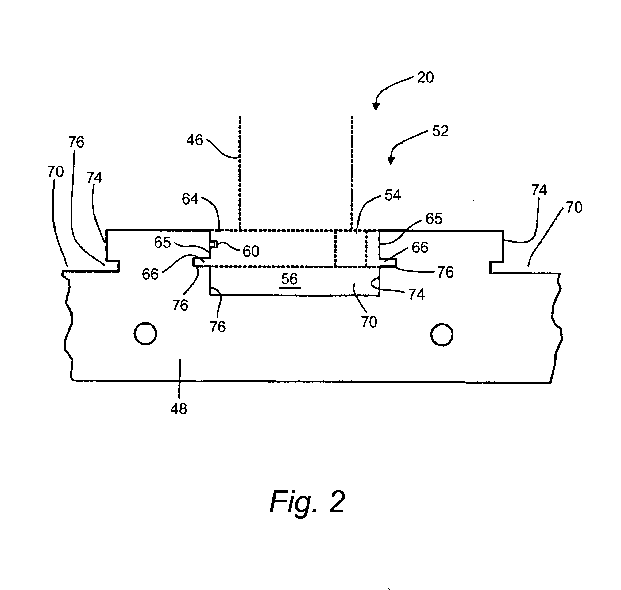
[0012]The invention provides a compressor stator vane unit and assembly wherein a link is provided between adjacent stator bases to reduce the likelihood of the stators rocking in the tangential direction. The resistance is created by transferring the outward radial force of one stator base to the inward radial force on the adjacent stator base. This resistance is transferred by the use of a metal strip which is set into a groove in the stator base. The stator base grooves are staked at each end of the set to prevent a link from shifting circumferentially.

[0013]Thus, an otherwise conventional stator base 64 is modified according to the invention to incorporate a groove spaced from the top of the base. A metal extrusion is slid into the groove of multiple adjoining stators. Then, as noted above, each end stator base is staked to prevent the metal extrusion from shifting. In the illustrated example embodiment, the groove is provided on only one side of the stator base to allow for ext...


PUM


Abstract

A compressor having a plurality of vane units each having at least one airfoil projecting from the base. Each base has a groove, so that when the vane units are disposed circumferentially adjacent, the grooves of the respective vane units are circumferentially aligned. A metal strip is disposed in the groove of a plurality of adjacent vane units to link the vane units forming a more rigid ring of vanes that are less susceptible to vane motion, e.g., caused by pressure fluctuations within the compressor of a gas turbine.

Description

BACKGROUND OF THE INVENTION[0001]Compressor stator vanes in an industrial gas turbine are loaded and unloaded during start-stop cycles. In addition, the vanes are subject to small pressure fluctuations during operation. These result in relative motion between the vane and the casing in which the vanes are assembled. This causes the hook-fit on the stator base and the corresponding portion of the casing to wear and eventually could lead to fracture. Failure along part of the stator hook-fit causes tipping of the stator ring, creating a flow path other than that in the original design.[0002]Previous solutions to this issue include a pinning method and a strapping method. The pinning method is disclosed in U.S. Pat. No. 6,984,108, the entire disclosure of which is incorporated herein by this reference. The pinning method uses a pin and hole method to link adjacent stators to form a rigid ring of stators. The strapping method, schematically illustrated in FIG. 1, provides a strap 10 tha...

Claims


Application Information

Patent Timeline
IPC IPC(8): F01D1/02
CPCF04D29/322F04D29/542F01D25/246F01D9/042F04D29/644
Inventor WICHMANN, LISAMARTIN, NICK
Owner GENERAL ELECTRIC CO
Why Eureka
Try Eureka