Guided detachable interlock and method of use

a detachable interlock and guide technology, applied in the field of guided detachable interlock and guide method of use, to achieve the effect of reducing movemen

Active Publication Date: 2009-02-12
BOSTON SCI SCIMED INC
View PDF14 Cites 18 Cited by
  • Summary
  • Abstract
  • Description
  • Claims
  • Application Information

AI Technical Summary

Benefits of technology

[0007]Described herein are systems and methods for delivering a detachable, implantable device. In one embodiment, a system includes a detachable link connecting the implantable device to a pusher wire, wherein the detachable link self-detaches after exiting a catheter lumen. The detachable link can include a guide member that inhibits detachment of the detachable link during transit through the catheter. For example, the detachable link can include first and second engaging members and the guide member can reduce the movement between the first and second engaging members by at least one degree of freedom.

Problems solved by technology

A perceived disadvantage of this method is that the electrolytic release of the coil requires a period of time to allow the connection to degrade, and therefore, rapid detachment of the coil from the pusher does not occur.

Method used


Image

  • Guided detachable interlock and method of use
  • Guided detachable interlock and method of use
  • Guided detachable interlock and method of use

Examples


Embodiment Construction

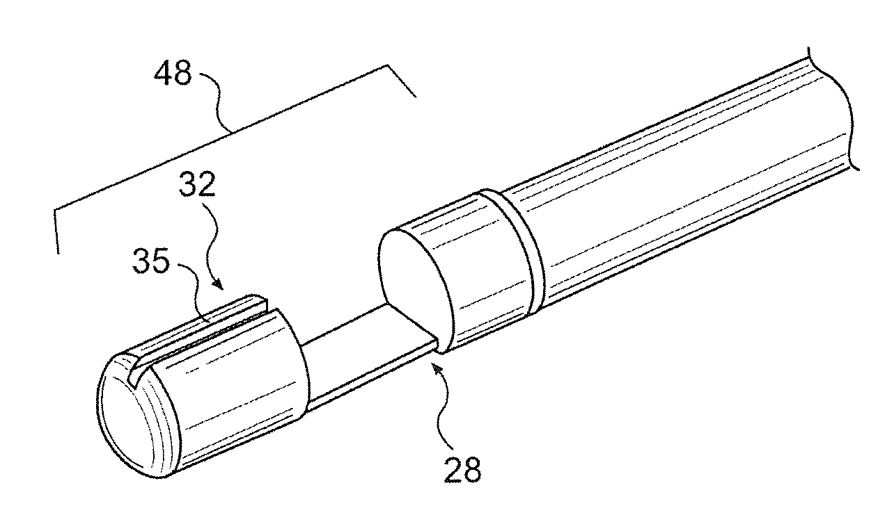
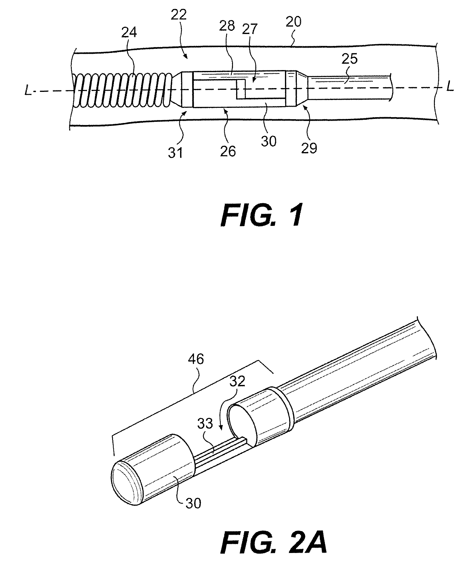
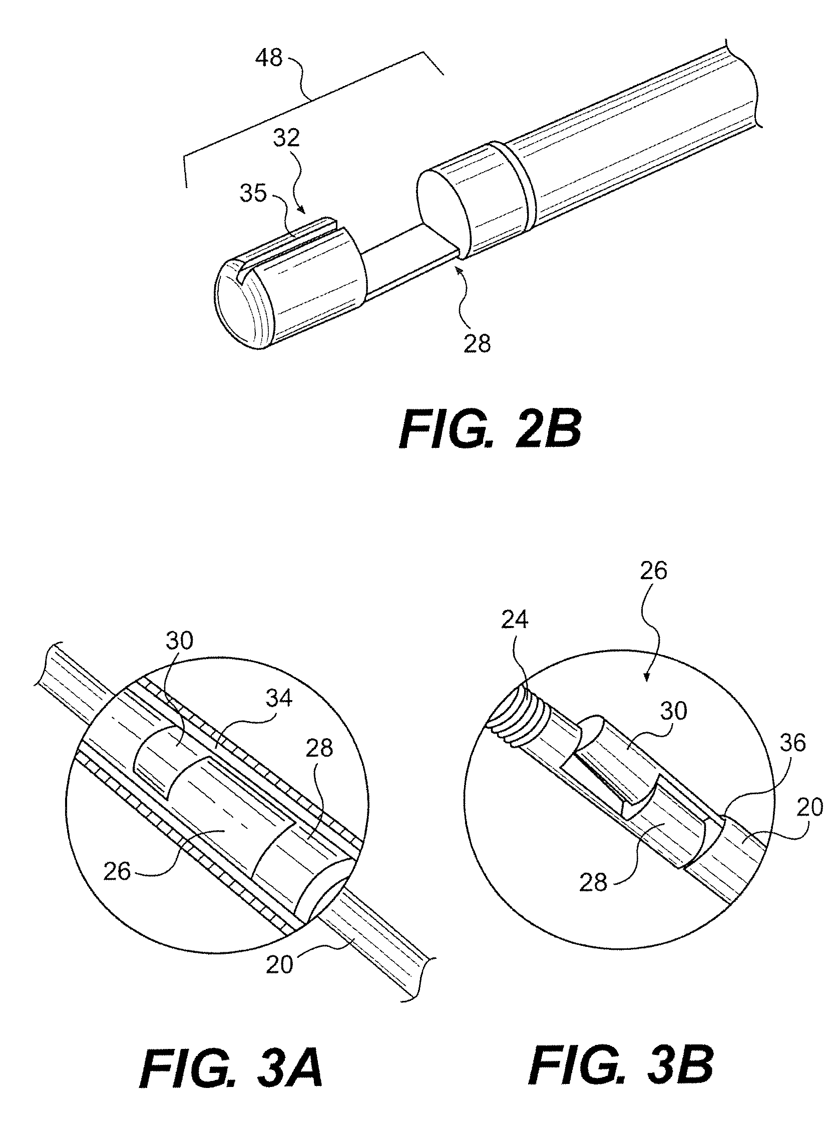
[0039]Disclosed herein are methods and systems for delivering an implantable device to a target site, particularly, a detachable, implantable device. The detachable, implantable device can be mated to a pusher wire via a detachable link that comprises first and second engaging members. Discussed below are a variety of detachable links which include features adapted to inhibit unwanted detachment during delivery of the implantable device through a catheter. In one embodiment, a guide member extends from a mating surface of the first and / or second engaging member and limits relative movement between the first and second engaging members. In another embodiment, a guide member positioned on an outer surface of the detachable link limits relative movement.

[0040]FIG. 1 shows a portion of catheter 20 cutaway to illustrate a system 22 for delivering an implantable device, in this case an embolic coil 24 (the terms “coil” and “embolic coil” are used interchangeably herein). The system includ...


PUM


Abstract

Described herein are various implant delivery methods and systems that include a detachable link for connecting an implantable device and a control wire. The detachable link can include an elongate body comprising a first arm with a mating surface having a slot extending the width of the elongate body and a second arm having a mating surface that includes a extension portion adapted to mate with the slot. A guide member can extend between the first and second arms and inhibit relative transverse and/or rotational movement between the first and second arms.

Description

[0001]This application claims priority to U.S. Provisional Application No. 60 / 954,883, entitled “GUIDED DETACHABLE INTERLOCK AND METHOD OF USE,” filed Aug. 9, 2007, which is incorporated by reference herein.BACKGROUND OF THE INVENTION [0002]The endovascular treatment of a variety of maladies throughout the body is an increasingly more important form of therapy. One such procedure uses embolizing coils to occlude a target site by posing a physical barrier to blood flow and / or by promoting thrombus formation at the site. Such treatments can be useful where it is desired to reduce vascularization, including treatments for aneurisms and cancer.[0003]Coils have typically been placed at the desired site within the vasculature using a catheter and a pusher. As a first step, a flexible, small diameter catheter can be guided to the target site through the use of guidewires or by flow-directed means such as balloons placed at the distal end of the catheter. Once the site has been reached, the...

Claims


Application Information

Patent Timeline
Patent Type & Authority Applications(United States)
IPC IPC(8): A61M29/02
CPCA61B17/12022A61B2017/12054A61B17/1214
Inventor BUISER, MARCIANARDONE, CHRISTOPHER
Owner BOSTON SCI SCIMED INC
Why Eureka
Try Eureka