Cartilage implant plug with fibrin glue and method for implantation

a cartilage implant and fibrin glue technology, applied in the field of surgical implants, can solve the problems of affecting the healing effect of articular cartilage lesions, affecting the healing effect of hyaline cartilage, and limiting the regeneration of hyaline cartilage, so as to increase the migration and proliferation of chondrocytes

Inactive Publication Date: 2009-02-12
MASSACHUSETTS INST OF TECH +1
View PDF99 Cites 29 Cited by
  • Summary
  • Abstract
  • Description
  • Claims
  • Application Information

AI Technical Summary

Problems solved by technology

If the lining becomes worn or damaged resulting in lesions, joint movement may be painful or severely restricted.
Whereas damaged bone typically can regenerate successfully, hyaline cartilage regeneration is quite limited because of its limited regeneration and reparative abilities.
Articular cartilage lesions generally do not heal, or heal only partially under certain biological conditions due to the lack of nerves, blood vessels and a lymphatic system.
The limited reparative capabilities of hyaline cartilage generally results in the generation of repair tissue that lacks the structure and biomechanical properties of normal cartilage.
Generally, the healing of the defect results in a fibrocartilaginous repair tissue that lacks the structure and biomedical properties of hyaline cartilage and degrades over the course of time.
These lesions are difficult to treat because of the distinctive structure and function of hyaline cartilage.
Osteoarthritis is the leading cause of disability and impairment in middle-aged and older individuals, entailing significant economic, social and psychological costs.
None of these therapies has resulted in the successful regeneration of hyaline-like tissue that withstands normal joint loading and activity over prolonged periods.
These techniques provide temporary pain relief, but have little or no potential for further healing.
Penetration into the subchondral bone induces bleeding and fibrin clot formation which promotes initial repair, however, the tissue formed is fibrous in nature and not durable.
There have also been problems with adhesion and stability of the grafts, which result in their displacement or loss from the repair site.
However, long term studies of this procedure in rabbits and dogs showed limited success and showed degradation at the implant site.
The original study report has been criticized for not being a prospective controlled randomized study and for lack of quantitative or mechanical.
As with the perichondrial graft, patient / donor age may compromise the success of this procedure as chondrocyte population decreases with increasing age.
Disadvantages to this procedure include the need for two separate surgical procedures, potential damage to surrounding cartilage when the periosteal patch is sutured in place, the requirement of demanding complex microsurgical techniques, and the expensive cost of the procedure which is currently not covered by insurance.
Factors that can compromise the results include donor site morbidity, effects of joint incongruity on the opposing surface of the donor site, damage to the chondrocytes at the articular margins of the donor and recipient sites during preparation and implantation, and collapse or settling of the graft over time.
The limited availability of sites for harvest of osteochondral autografts restricts the use of this approach to treatment of relatively small articular defects and the healing of the chondral portion of the autograft to the adjacent articular cartilage remains a concern.
Drawbacks associated with this methodology in the clinical situation include the scarcity of fresh donor material and problems connected with the handling and storage of frozen tissue.
Fresh allografts carry the risk of immune response or disease transmission.
Frozen allografts lack cell viability and have shown a decreased amount of proteoglycan content which contribute to deterioration of the tissue.
The use of implants for cartilage defects is much more limited.
Concerns associated with this method are harvest site morbidity and availability, similar to the mosaicplasty method.

Method used


Image

  • Cartilage implant plug with fibrin glue and method for implantation
  • Cartilage implant plug with fibrin glue and method for implantation
  • Cartilage implant plug with fibrin glue and method for implantation

Examples


example 1

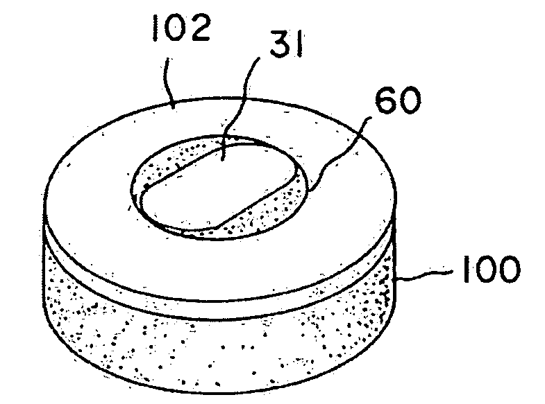
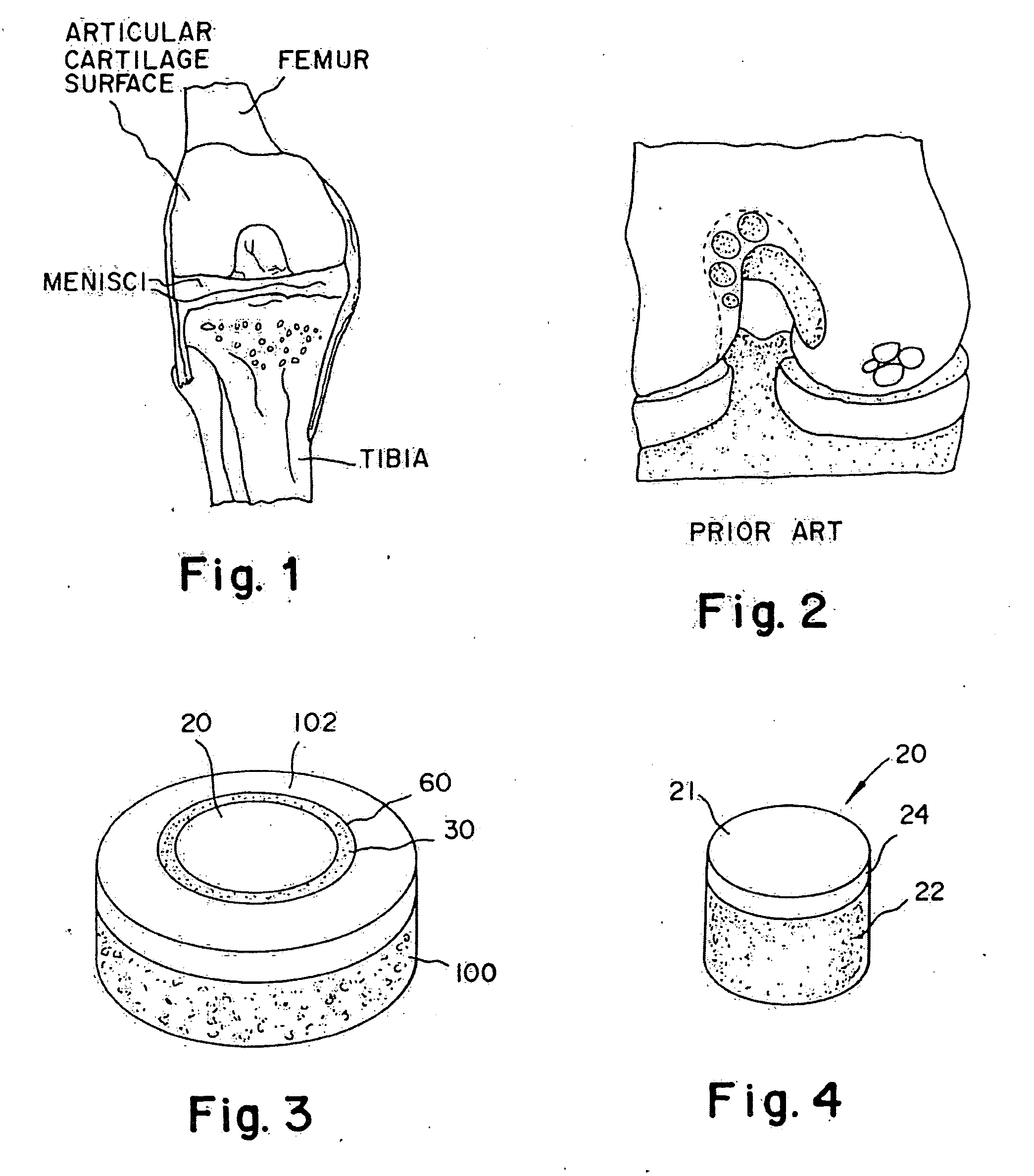
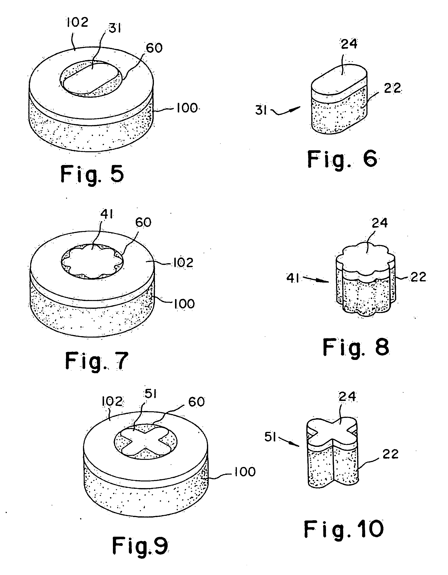
[0042]A non-viable or decellularized osteochondral plug consisting of a subchondral bone base and overlying cartilage cap is treated with a solution or variety of solutions to remove the cellular debris as well as the proteoglycans as noted in the treatment described above. It is believed that this removal provides signaling to stimulate the surrounding chondrocytes and also the host's bone marrow and other mesenchymal stem cells to migrate into the graft to proliferate and form new proteoglycans and other factors producing new matrix. The diameter or diagonal of the plug ranges from 1 mm to 30 mm but is preferably 4 mm to 10 mm which is small enough to fit through the endoscopic cannula, but large enough to minimize the number of plugs needed to fill large defects. This size provides good results at the recipient site and provides a more confluent hyaline surface. The thickness of subchondral bone can be modified to match the anatomy of the patient so that the surface cartilage of ...


PUM

PropertyMeasurementUnit
sizeaaaaaaaaaa
particle sizeaaaaaaaaaa
molecular weightaaaaaaaaaa

Abstract

The invention is directed toward a cartilage repair assembly comprising a shaped structure of subchondral bone with an integral overlying cartilage cap which is treated to remove cellular debris and proteoglycans and milled cartilage in a bioabsorbable carrier. The shaped structure is dimensioned to fit in a drilled bore in a cartilage defect area so that said shaped bone and cartilage cap when centered in the bore does not engage the side wall of the bore in an interference fit and is surrounded by milled cartilage and carrier. A method for inserting the assembly into a cartilage defect area is disclosed.

Description

RELATED APPLICATIONS[0001]This is a divisional application of U.S. patent application Ser. No. 10 / 815,778 filed Apr. 2, 2004, which is incorporated by reference herein in is entirety.FIELD OF INVENTION[0002]The present invention is generally directed toward a surgical implant and is more specifically directed toward an implant for a joint having a cartilage face and bone body for implantation in a shoulder, hip, elbow, ankle, knee or temporomandibular joint.BACKGROUND OF THE INVENTION[0003]Articular cartilage injury and degeneration present medical problems to the general population which are constantly addressed by the orthopedic surgeon. Every year in the United States, over 500,000 arthroplastic or joint repair procedures are performed. These include approximately 125,000 total hip and 150,000 total knee arthroplastics and over 41,000 open and arthroscopic procedures to repair cartilaginous defects of the knee. Chen et al. “Repair of Articular Cartilage Defects: Part 1, Basic Sci...

Claims


Application Information

Patent Timeline
Patent Type & Authority Applications(United States)
IPC IPC(8): A61F2/08A61F2/00A61F2/28A61F2/30A61L27/36A61L27/48
CPCA61B17/00491A61L2430/06A61F2/30756A61F2/3094A61F2/3859A61F2/4644A61F2002/2817A61F2002/2839A61F2002/2867A61F2002/30004A61F2002/30062A61F2002/30112A61F2002/30113A61F2002/30121A61F2002/30125A61F2002/30136A61F2002/30153A61F2002/30179A61F2002/30224A61F2002/30225A61F2002/30228A61F2002/3028A61F2002/30759A61F2002/30764A61F2002/4635A61F2210/0004A61F2230/0004A61F2230/0006A61F2230/0008A61F2230/0019A61F2230/0058A61F2230/0063A61F2230/0069A61F2250/0014A61F2310/00365A61F2310/00383A61L27/3608A61L27/3612A61L27/3654A61L27/3683A61L27/48A61L27/52A61F2/28A61F2002/2835A61L27/3804
Inventor VUNJAK-NOVAKOVIC, GORDANAGERTZMAN, ARTHUR A.SUNWOO, MOON HAETOMFORD, WILLIAM W.TRUNCALE, KATHERINE G.
Owner MASSACHUSETTS INST OF TECH
Why Eureka
Try Eureka