Method for calculating an approach trajectory of an aircraft to an airport

Inactive Publication Date: 2009-02-12
THALES SA
View PDF14 Cites 48 Cited by
  • Summary
  • Abstract
  • Description
  • Claims
  • Application Information

AI Technical Summary

Benefits of technology

[0013]Another advantage of the invention is that it requires only the modification of the software part of the existing flight management systems. In particular, no modification of the automatic pilot or of the auto-throttle regulating the thrust is required.
[0014]For this purpose, the subject of the invention is a method for calculating an approach trajectory of an aircraft to a runway of an airport, the aircraft being slaveable in terms of trajectory and speed, in terms of trajectory and thrust or in terms of thrust and speed, the aircraft being able to advance at reduced engine revs, the approach trajectory terminating in an impact point on the runway and comprising a high-altitude descent segment constructed on the basis of a thrust and speed setpoint, and an intermediate geometric segment constructed on the basis of speed and slope setpoints appending altitude constraints, to which the aircraft is slaved in terms of trajectory and thrust and then trajectory and speed, wherein comprising a step of calculating a final approach segment at reduced engine revs and a landing segment preparing a possible go-around, to which the aircraft is slaved in terms of thrust and speed.
[0015]Advantageously, the method for calculating an approach trajectory according to the invention furthermore comprises a step of automatic monitoring of the position of the impact point on the runway, the step comprising: real-time evaluation of the position and speed of the impact as a function of the position and current speed of the aircraft, propagated up to the runway with the conditions regardin

Problems solved by technology

This induces an approach trajectory that is close to the ground for quite some time, this being detrimental for the local residents as regards noise.
Moreover, maintaining a constant

Method used


Image

  • Method for calculating an approach trajectory of an aircraft to an airport
  • Method for calculating an approach trajectory of an aircraft to an airport
  • Method for calculating an approach trajectory of an aircraft to an airport

Examples


Example

DETAILED DESCRIPTION OF THE DRAWINGS

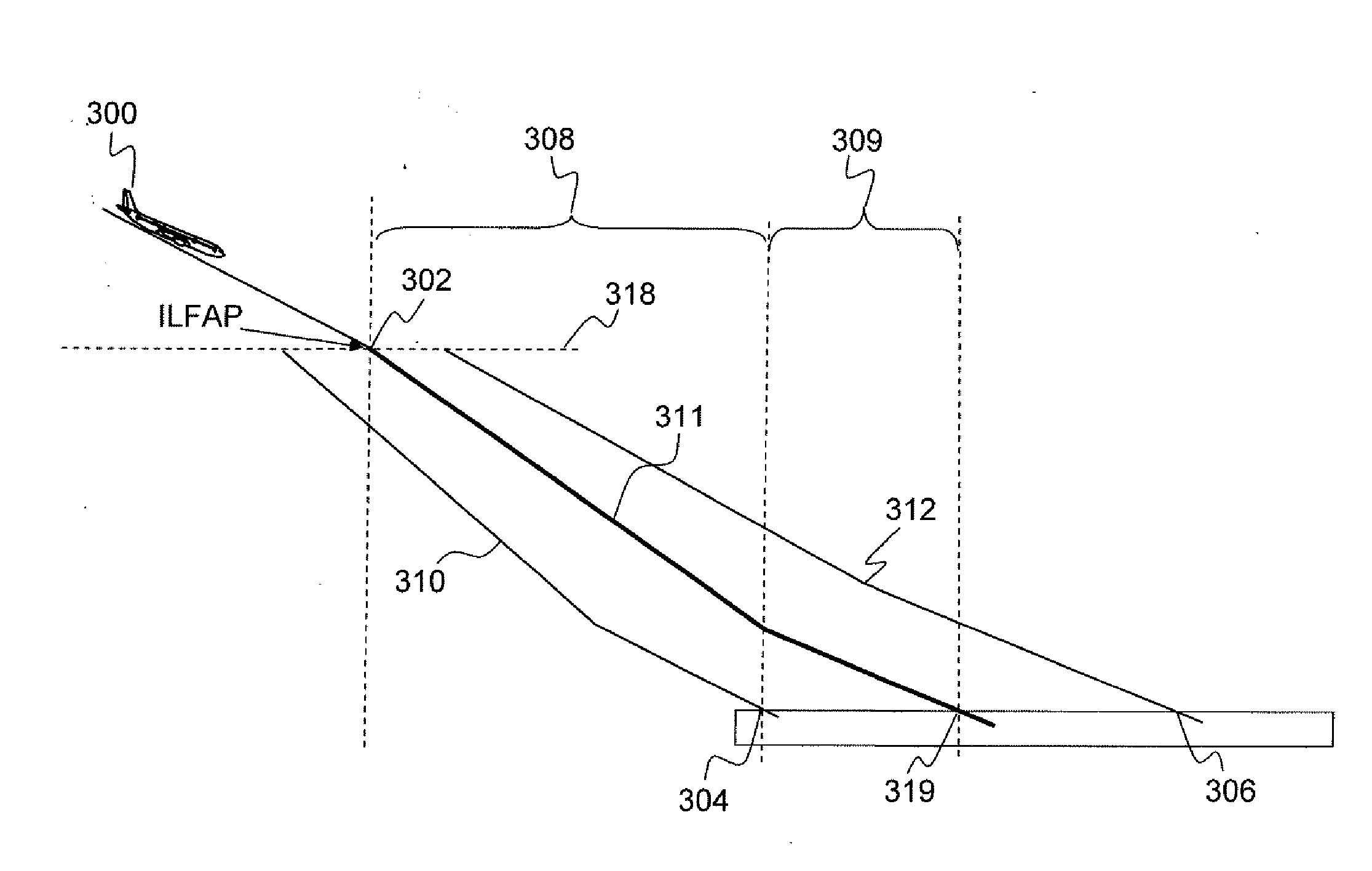
[0035]The present invention relates to a method for calculating an approach trajectory of an aircraft 200 to an airport. The airport comprises a runway 216. The runway 216 is characterized by two extreme points: a runway threshold 213, before which no impact is possible without danger, and a limit extreme point 214, beyond which no impact is possible without danger to terminate the landing and disengage to the exit linkway with a stabilized and controlled speed. Beyond the limit extreme point 214, the aircraft no longer has enough distance to brake before the runway extremity or the exit linkway. In an arbitrary manner, the limit extreme point 214 is fixed at 25% of the runway length starting from the threshold. However, this value can be modified depending on need and local conditions.

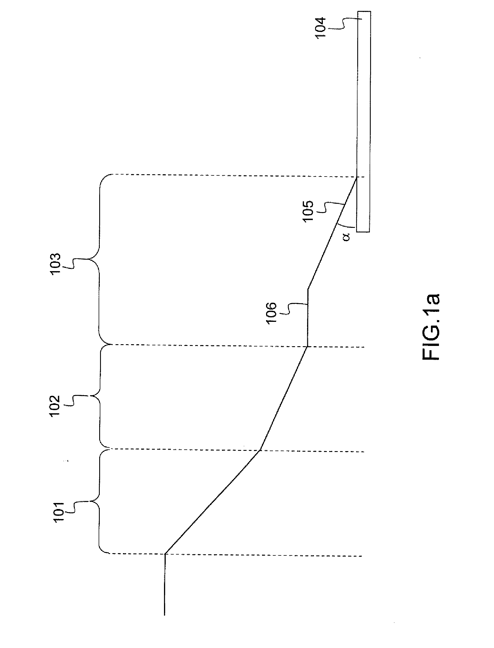
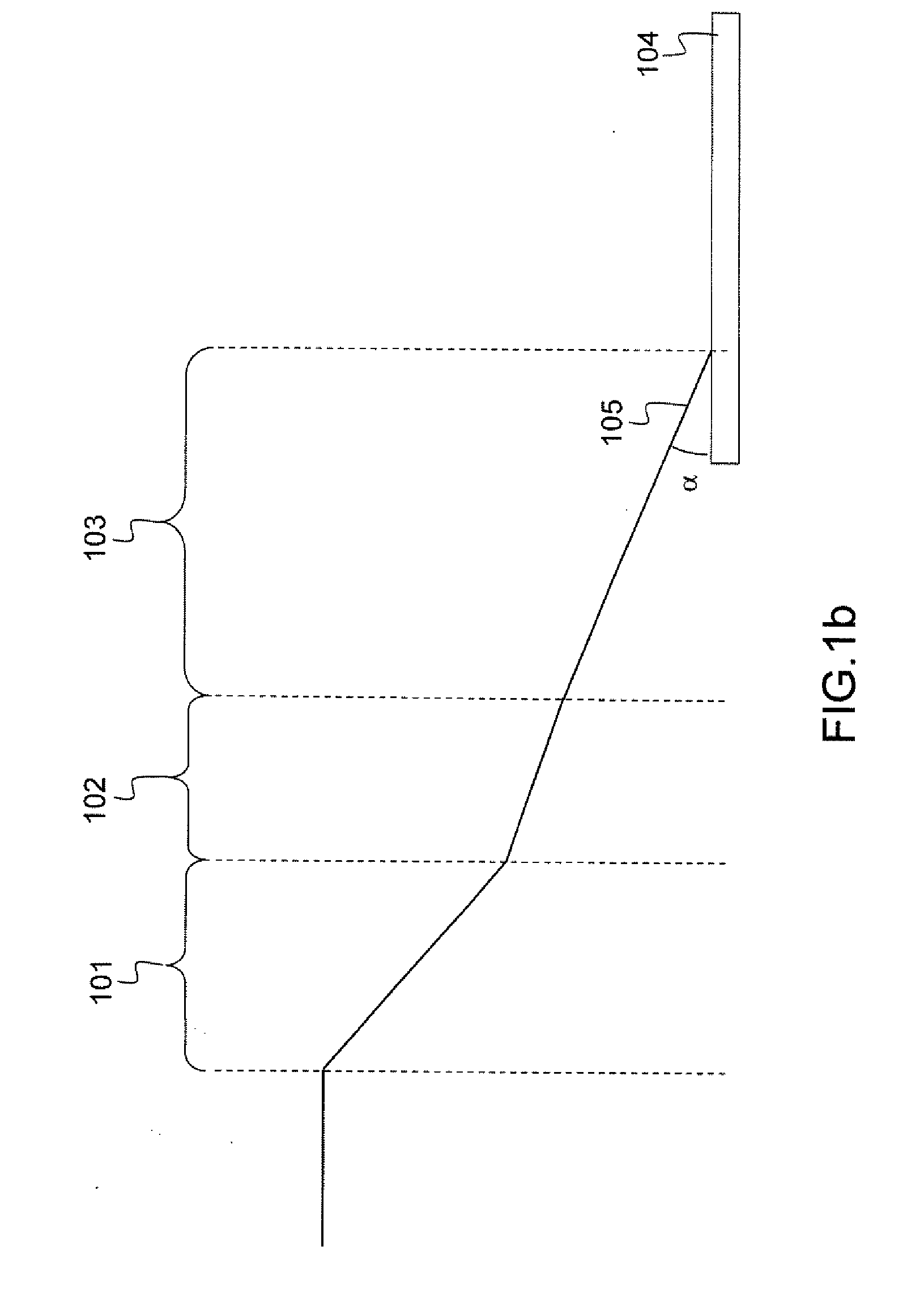
[0036]A first segment is a high-altitude descent segment 217. The high-altitude descent segment 217 starts from a point at which descent begins (called “Top Of Desc...


PUM


Abstract

The invention relates to a method for calculating an approach trajectory of an aircraft (200) to an airport The aircraft is slaveable in terms of trajectory, thrust and/or speed. The aircraft is able to advance at reduced engine revs. The airport has a runway The approach trajectory terminates in an impact point (205) on the runway and has a high-altitude descent segment (217) and an intermediate geometric segment (207), to which the aircraft is slaved in terms of trajectory and speed. A step of calculating a final approach segment (208) at reduced engine revs and a landing segment is performed with a greater thrust than the reduced revs so as to prepare a possible go-around (209), to which the aircraft is slaved in terms of thrust and speed.

Description

RELATED APPLICATIONS[0001]The present application is based on, and claims priority from, French Application Number 07 02971, filed Apr. 24, 2007, the disclosure of which is hereby incorporated by reference herein in its entirety.FIELD OF THE INVENTION[0002]The invention relates to flight management systems and, more particularly to the calculation of an approach trajectory of an aircraft to an airport.BACKGROUND OF THE INVENTION[0003]Flight safety is the first priority of airlines, followed by in-flight comfort and operating costs. Another constraint occurs today with the environment: reduction of impacts in terms of noise for the local residents and emission of pollutants.[0004]Currently, descent trajectories generally terminate at constant slope at the time of landing so as to be compatible with the landing means which are materially defined with a constant slope setting (or “Glide slope” as it is known). These trajectories are compatible with all aeroplanes a priori and furthermo...

Claims


Application Information

Patent Timeline
IPC IPC(8): G06F19/00
CPCG05D1/0676Y02T50/84G08G5/025Y02T50/80
Inventor DEKER, GUY
Owner THALES SA
Why Eureka
Try Eureka