
Method and device for calculating magnitude of cornering force generated in wheel

a technology of cornering force and calculating method, which is applied in the field of cornering force calculating method and cornering force calculating device, can solve the problems that the accuracy of reproducing of known indoor cornering test devices is limited and the measurement of cornering force generated on the contact surface of specific tires cannot be determined. achieve the effect of accurately calculating the magnitude of a cornering for

Inactive Publication Date: 2009-02-12
YOKOHAMA RUBBER CO LTD
View PDF4 Cites 9 Cited by
  • Summary
  • Abstract
  • Description
  • Claims
  • Application Information

AI Technical Summary

Benefits of technology

[0016]According to the cornering force calculating method and the cornering force calculating device of the present invention, it is possible to accurately calculate with ease a magnitude of a cornering force generated in each of a plurality of wheels actually mounted on a vehicle when the vehicle is cornering.

Problems solved by technology

Thus, known indoor cornering test devices have had a limitation in accuracy in reproducing various conditions that the vehicle may encounter after actual mounting of the tire thereon and during actual traveling on the road surface (e.g., condition of load applied to the tire, tire rotating condition).
Thus, with such indoor cornering test devices, when a specific tire is actually mounted to a vehicle, accurate measurement of the cornering force generated on a contact surface of the specific tire cannot be determined.

Method used


Image

  • Method and device for calculating magnitude of cornering force generated in wheel
  • Method and device for calculating magnitude of cornering force generated in wheel
  • Method and device for calculating magnitude of cornering force generated in wheel

Examples


Embodiment Construction

[0047]A cornering force calculating method and a cornering force calculating device of the present invention will hereinafter be described in detail with reference to a preferred embodiment shown in the accompanying drawings.

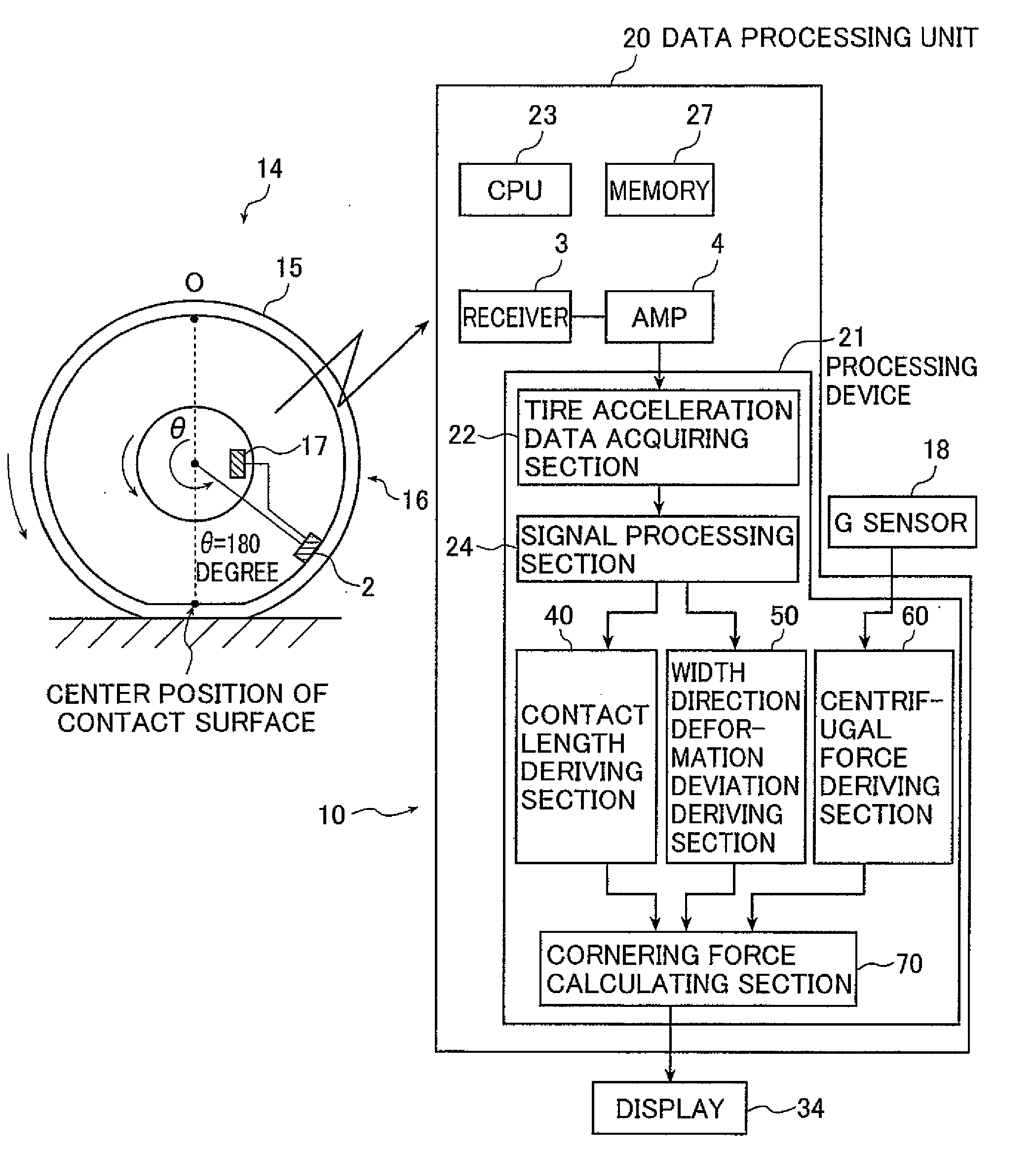
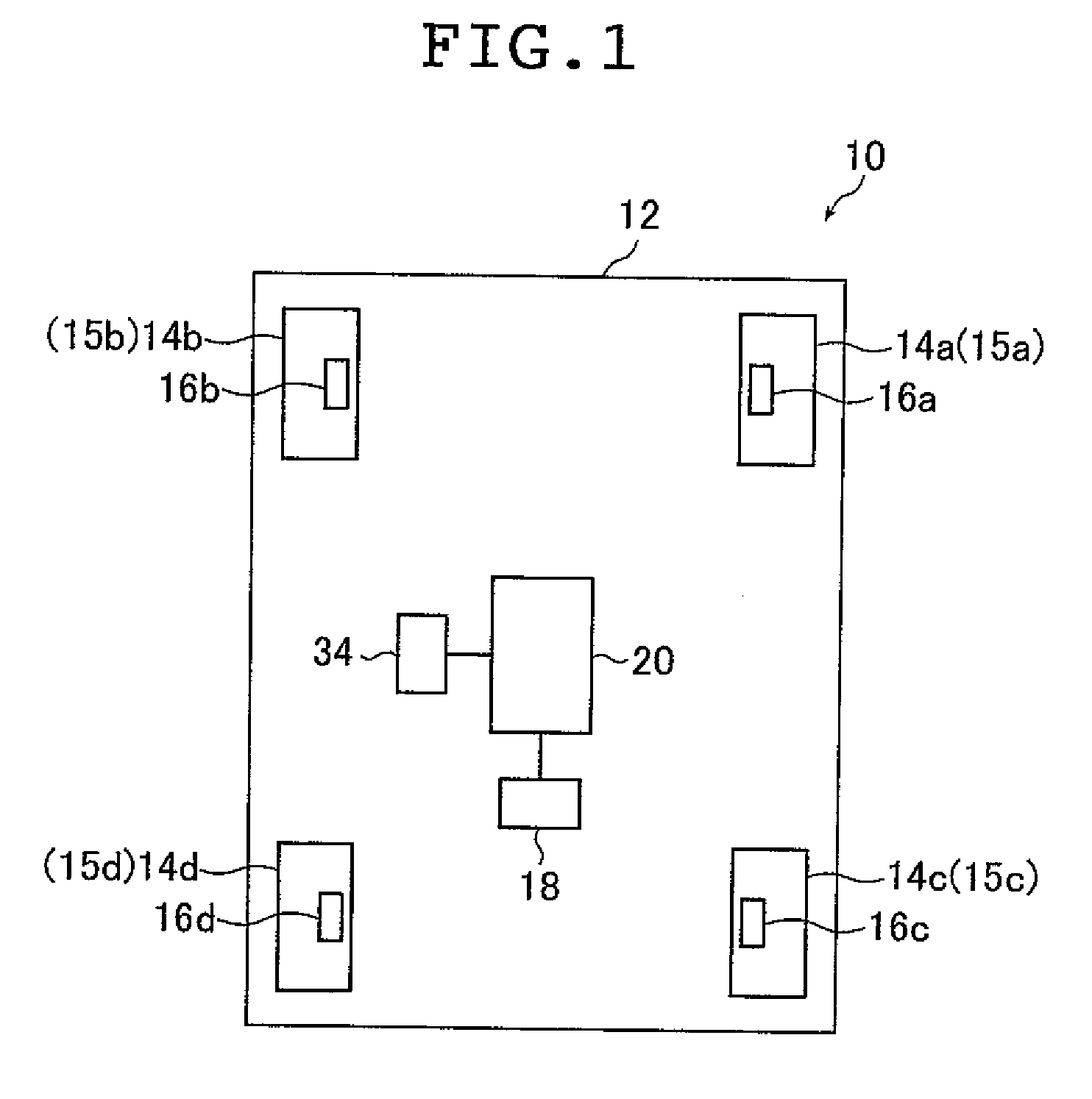
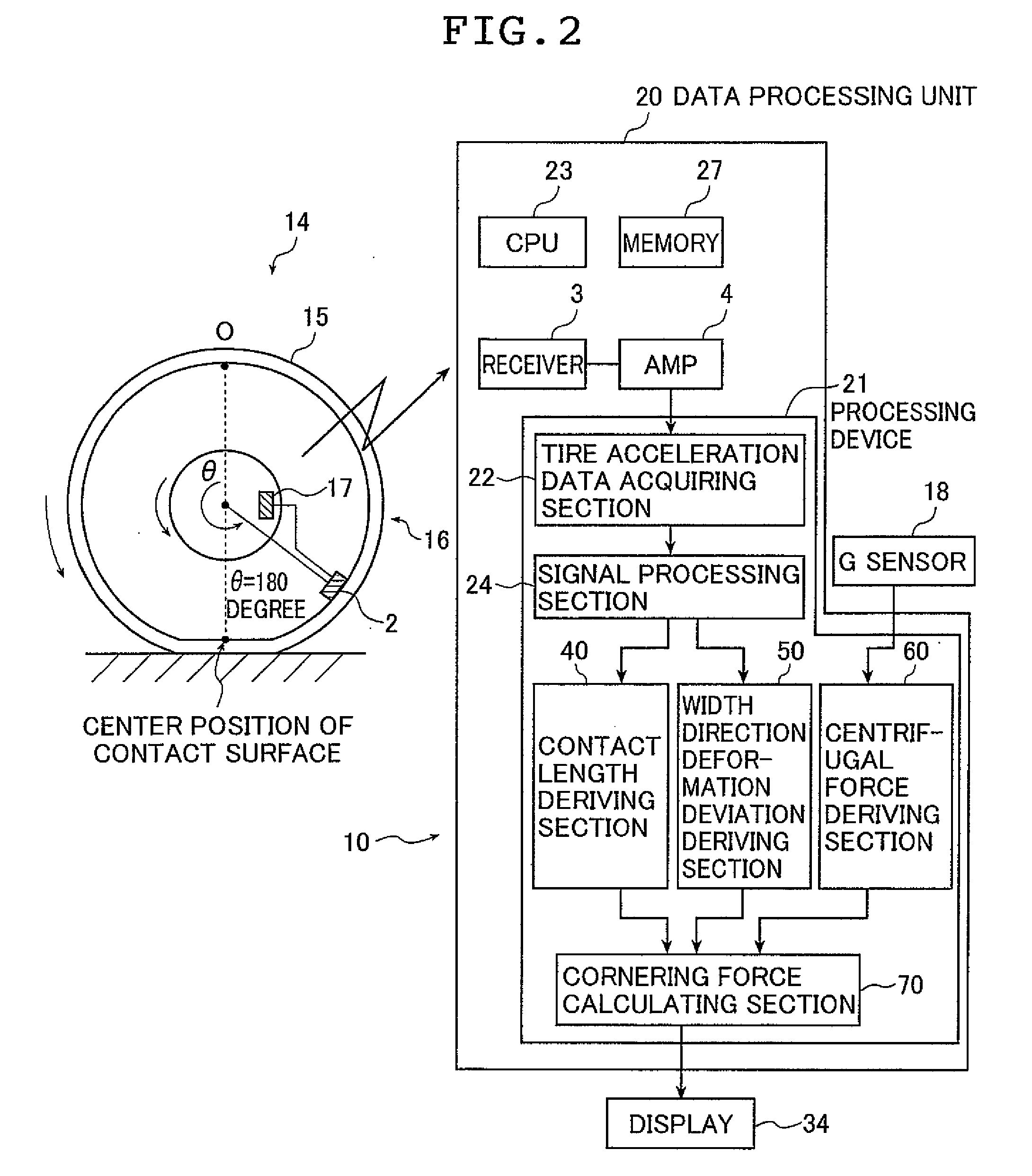
[0048]FIG. 1 shows a schematic view explaining a cornering force calculating device 10 (hereinafter, referred to as device 10), which is an example of the cornering force calculating device according to the present invention. The device 10 is provided on a vehicle 12 to which four wheels 14a to 14d are mounted. The four wheels 14a to 14d have tires 15a to 15d that are assembled to the wheels 14a to 14d, respectively. All of the tires 15a to 15d are the same in type (same in tire size, tire rim width, belt structure, tire pressure level, or the like). The device 10 includes sensor units 16a to 16d, an acceleration sensor (G sensor) 18, a data processing unit 20, and a display 34. The sensor units 16a to 16d are each provided to the four wheels 14a to 14d, respect...


PUM


Abstract

A method of calculating a cornering force to be applied to each wheel provided to a vehicle which is cornering, comprising the steps of: obtaining a magnitude of a centrifugal force to the vehicle in a direction substantially orthogonal to a vehicle traveling direction, a contact length of each wheel during the cornering of the vehicle, and an amount of deformation in a wheel width direction at the contact portion of each wheel of the vehicle, calculating a difference between the obtained amount of the deformation and an amount of deformation in the wheel width direction under a straight forward travel condition of the vehicle for each wheel, and calculating a cornering force for each wheel based on the magnitude of the centrifugal force, the contact length, and the difference between amounts of deformation in the wheel width direction.

Description

TECHNICAL FIELD[0001]The present invention relates to a cornering force calculating method and a cornering force calculating device for calculating a magnitude of a cornering force generated in each of a plurality of wheels provided to a vehicle when the vehicle is cornering.BACKGROUND ART[0002]The cornering property is a key factor for the driveability of automobile vehicles. In order to design automobile vehicles capable of achieving higher driveability, it is important to evaluate the cornering property of the automobile vehicle accurately. For an automobile vehicle provided with wheels to which tires are mounted, various factors are involved in its cornering property, including vehicle structure properties (e.g., weight, balance), suspension properties, tire properties, and road surface conditions. When an automobile vehicle is cornering, an equilibrium state is maintained between the sum of the forces (cornering forces) towards the center of the cornering line generated on the ...

Claims


Application Information

Patent Timeline
IPC IPC(8): G01L5/00B60C23/06B60R16/027B60W10/00B60W30/00B60W40/10B60W40/109B60W40/114B60W40/12G01M17/02G01M17/06
CPCB60G2400/104B60G2400/64B60G2400/824B60G2800/24B60T2240/04B60W30/02B60W2550/402B60W30/18172B60W40/00B60W40/064B60W40/101B60W2520/125B60W2530/20B60W30/095B60W2556/50
Inventor MATSUDA, JUNKITAZAKI, TSUYOSHIMIYASHITA, NAOSHI
Owner YOKOHAMA RUBBER CO LTD
Learn More