Agricultural working machine

a working machine and working technology, applied in the field of agricultural working machines, can solve the problems of difficult to find, no optimised position of the spout, and the driver can quickly become overloaded, so as to improve the visibility of the illuminated area and improve the visibility of the crop stream

Inactive Publication Date: 2009-02-19
AGROCOM & AGRARSYST
View PDF6 Cites 207 Cited by
  • Summary
  • Abstract
  • Description
  • Claims
  • Application Information

AI Technical Summary

Benefits of technology

[0028]For improving the visibility conditions of the crop stream and / or the position of the storage container detected by the electro-optical device, provision is made, to use a electro-optical device consisting of at least one camera and at least one light source, illuminating the crop stream and / or the storage container detected by the camera, whereas the at least one light source could be attached to the spout of the forage harvester and / or the chassis of the forage harvester and / or the transport vehicle. The same effect can be achieved, if the illuminating direction of the at least one light source differs from the viewing direction of the camera. In a preferred solution the at least one light source illuminates the crop stream transversally and / or in an opposite direction to the viewing direction of the camera. Such an arrangement ensures that a light scattering, based on reflection of light waves on crop stream pieces, will be avoided, what improves the visibility of the illuminated area.

Problems solved by technology

The essential disadvantage of a product jet detection device thus structured is that the operator of the agricultural working machine must draw the correct conclusions from the images generated by the camera and finally carry out the position adaptation of the spout himself.
Because the operator of the agricultural working machine must monitor and control a multiplicity of machine functions in the harvesting process, the driver can quickly become overloaded by this on the one hand.
On the other hand the optimised position adjustment of the spout depends substantially on the skills of the driver and, depending on experience, may vary considerably from driver to driver, so that sometimes no optimised position of the spout is found, or it is difficult to find it.
An essential disadvantage of control system structured in this manner is that the possibilities of guiding the project jet depend on the kinematic possibilities of the spouts themselves.

Method used


Image

  • Agricultural working machine
  • Agricultural working machine
  • Agricultural working machine

Examples


Embodiment Construction

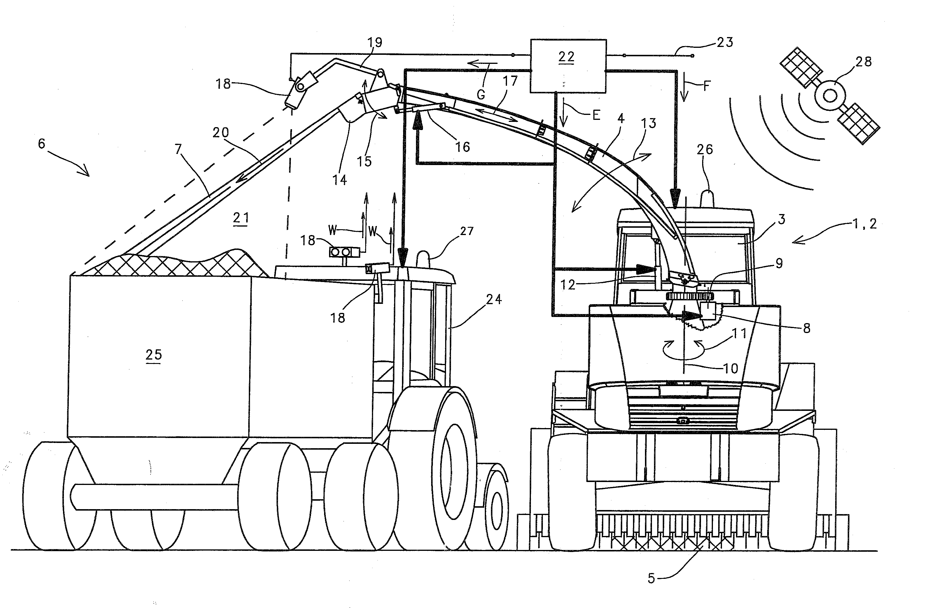
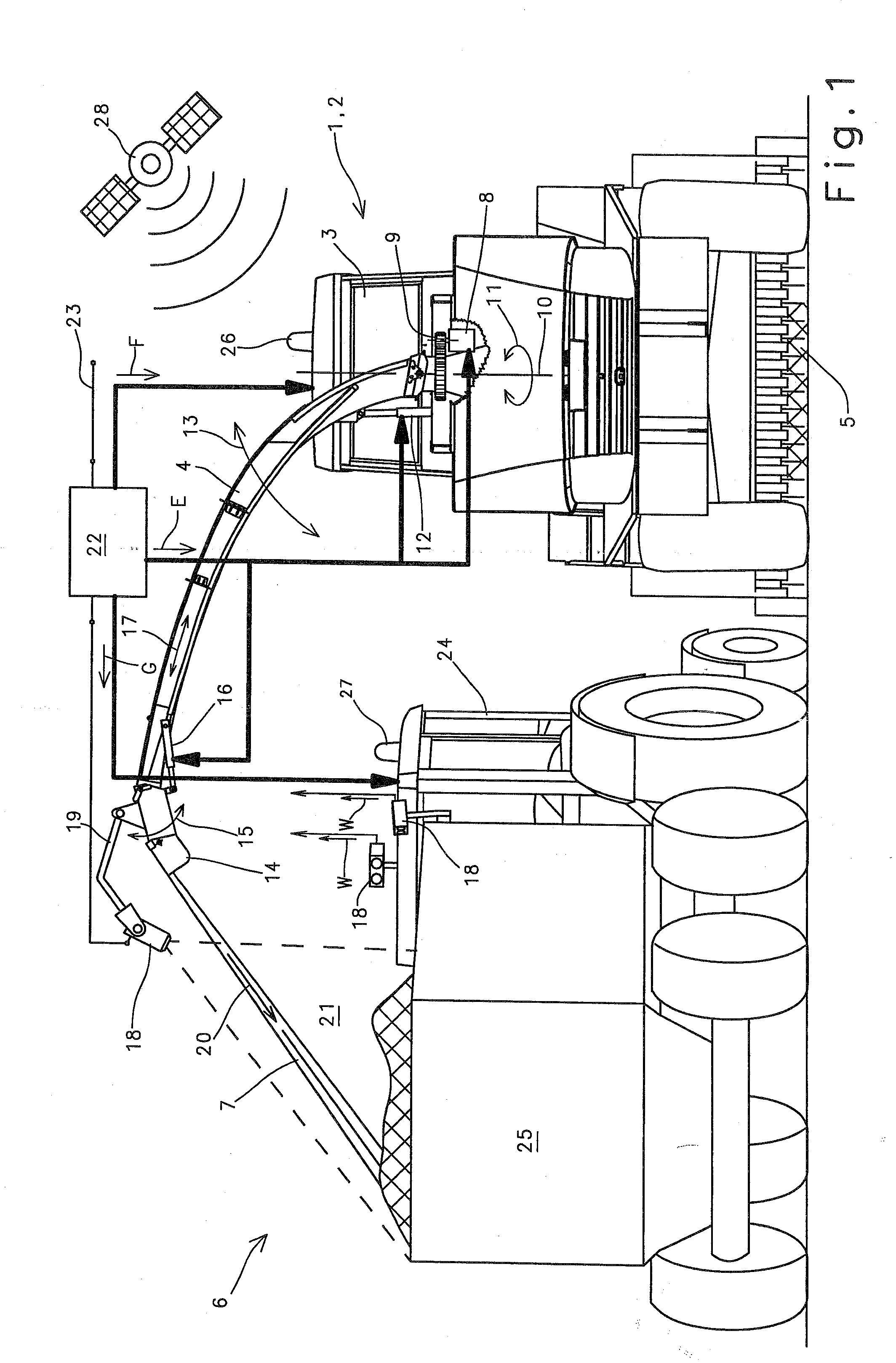
[0034]FIG. 1 shows an agricultural working machine 1 designed as a forage harvester 2, which is provided in its region arranged downstream of driver's cab 3 with a spout 4 for transferring the crop 5 received and processed by forage harvester 2 to a transport vehicle 6. To ensure that spout 4 is able, very flexibly, to transfer crop flow 7 to transport vehicle 6, spout 4 is assigned in its lower side region with a gear stage 9 that can be driven by means of a hydraulic or electric motor 8. When this gear stage 9 is activated, spout 4 can be swiveled about a vertical axis 10 according to arrow direction 11. Moreover, spout 4 is assigned, in a vertical alignment, at least one lifting cylinder 12, spout 4 being capable of performing a vertical pivoting movement according to arrow direction 13 when the lifting cylinder 12 undergoes pressure loading or pressure relief. On its upper-side end spout 4 is assigned, by a known method, a discharge cap 14 so that it can be moved pivotably, the ...


PUM


Abstract

The invention relates to an agricultural working machine (1), in particular a forage harvester (2), with at least one spout (4) for conveying received and processed crop (7) to a transport vehicle (6, 25), wherein an electro-optical device (18) is provided for the direction control of the spout (4) at least during the process of conveying to the transport vehicle (6, 25), and wherein the electro-optical device (18) detects characteristic parameters (30) of the spout (4) and characteristic parameters (30) of the transport vehicle (6) and/or the agricultural working machine (1). This ensures that a control of a spout (4) of agricultural working machines (1, 2) is provided which almost completely relieves the operator of the agricultural working machine (1, 2) of the task of monitoring the spout.

Description

CROSS-REFERENCE TO A RELATED APPLICATION[0001]The invention described and claimed hereinbelow is also described in European Patent Application EP 07015319.3 filed on Aug. 3, 2007. This European Patent Application, subject matter of which is incorporated herein by reference, provides the basis for a claim of priority of invention under 35 U.S.C. 119(a)-(d).BACKGROUND OF THE INVENTION[0002]The invention relates to an agricultural working machine with at least one spout.[0003]DE 44 26 059 discloses a generic agricultural working machine designed as a forage harvester to whose spout is assigned a camera which detects both the end region of the spout and the loading space of the trailer. Furthermore, a monitor is provided in the vicinity of the driver's seat arranged in the vehicle cab, on which monitor are visualised the sequences recorded by the camera in such a manner that both the end region of the spout and the loading space of the transport container are visualised in one and the s...

Claims


Application Information

Patent Timeline
Patent Type & Authority Applications(United States)
IPC IPC(8): A01D57/00
CPCA01D43/087
Inventor HUSTER, JOCHENMOELLER, JENSDIEKHANS, NORBERTAUTERMANN, LUDGERNIENABER, GERHARDHIERONYMUS, PETERWILKEN, ANDREASPEIN, CHRISTOPHRECKERMANN, MICHAELKLEINGRAEBER, KARL-JOSEFERDMANN, HUBERTMADSEN, TOMMYKIRK, KRISTIANVILANDER, JESPERBLAS, RUFUSKILDEBY, ALLAN
Owner AGROCOM & AGRARSYST
Why Eureka
Try Eureka