
Ice dispenser for a refrigerator

a technology for refrigerators and ice dispensers, applied in the direction of liquid bottling, coin-freezing apparatus, electromagnets, etc., can solve problems such as unpleasant humming noise, and achieve the effect of preventing fingers from potentially becoming jammed

Active Publication Date: 2009-02-19
EMZ HANAUER
View PDF4 Cites 15 Cited by
  • Summary
  • Abstract
  • Description
  • Claims
  • Application Information

AI Technical Summary

Benefits of technology

[0013]With the solution according to the invention, only a brief, that is to say, pulse-like supply of electrical power is required for the actuating magnet arrangement in order to transfer the flap unit from one of its positions into the other. The mechanical retention means which are separate from the actuating magnet arrangement bring about the stable retention of the flap unit in each of the two positions thereof, and consequently it is not necessary to continuously supply the actuating magnet arrangement with electrical power in either of the two positions in order to retain it at that location. This allows humming noises of the actuating magnet arrangement to be prevented or at least significantly reduced and also serves to reduce the power consumption. The retention means can even support the movement of the flap unit at least from a specific point of its movement path, which allows the electrical power supply already to be removed before reaching the other flap position in each case and consequently allows a further reduction of consumption. To this end, the retention means may comprise in particular appropriate resilient means.
[0016]Between the guide track member and the retention finger, a resiliently flexible bias arrangement may be effective whose bias force is intended to be overcome in order to release the flap unit from at least one, in particular from each of the two positions thereof. The bias force of the bias arrangement can ensure the stability of the guiding finger in the rest positions and consequently the stability of the flap unit in the two positions thereof. At least one of the rest positions, in particular the one with the larger bias force of the bias arrangement, can be defined by the guide track member. The other rest position can be defined, for example, by a stop contact of two components of the ice dispenser outside the guide track member or it can also be defined by the guide track member itself. In the release position of the flap unit, the bias force to be overcome may be greater than in the locking position, although alternatively it is also possible to select a transposed solution.
[0024]Irrespective of the specific configuration of the retention means, the flap unit may have movement in terms of play relative to an armature of the actuating magnet arrangement that is coupled to the flap unit in terms of driving. Such movement in terms of play may be advantageous in order to prevent an occurrence of sudden movement into the other flap position owing to manual “tampering” at the flap position, and to prevent fingers from potentially becoming jammed.

Problems solved by technology

It has been found that this solution may involve a humming noise which is perceived to be unpleasant.

Method used


Image

  • Ice dispenser for a refrigerator
  • Ice dispenser for a refrigerator
  • Ice dispenser for a refrigerator

Examples


Embodiment Construction

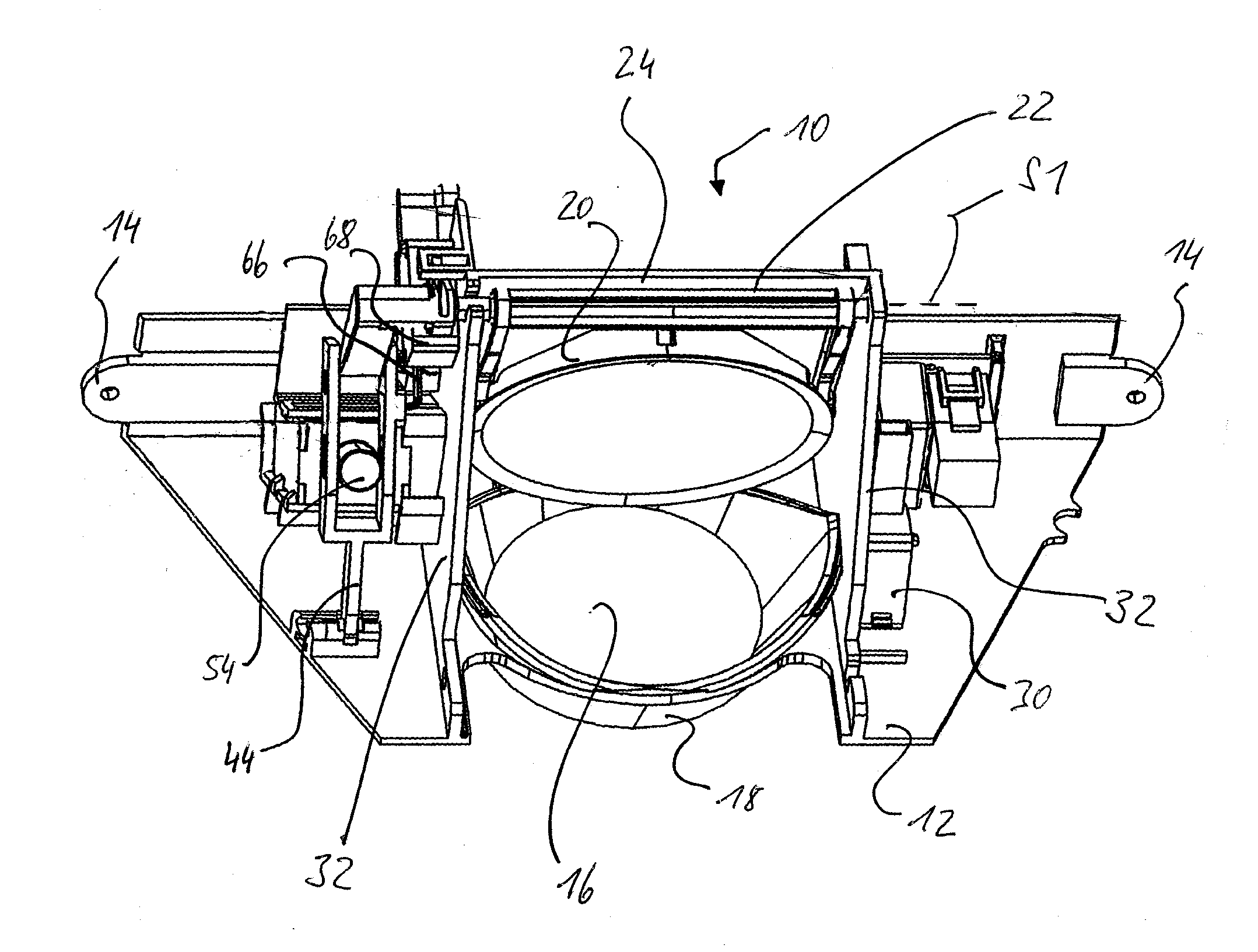
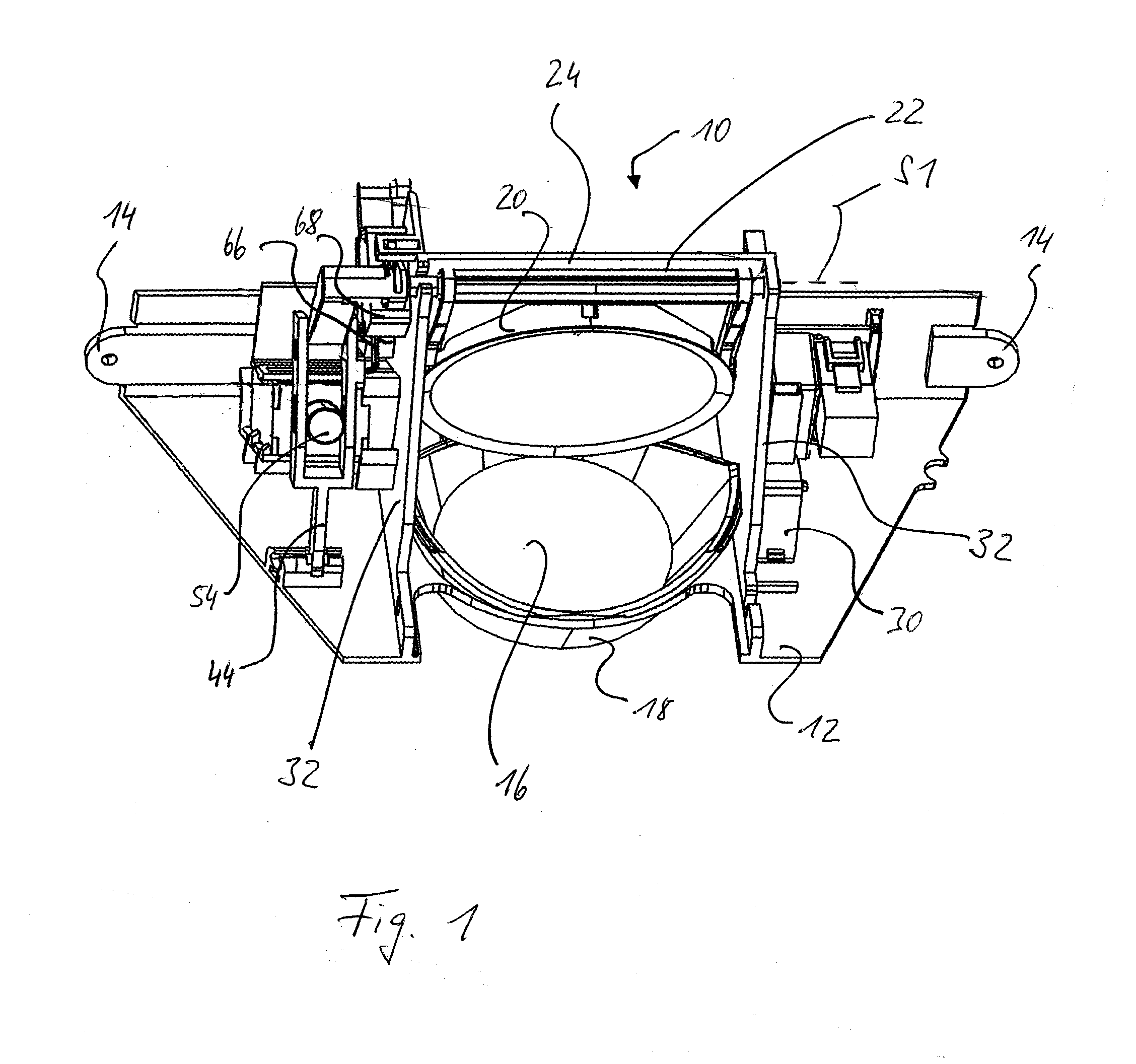
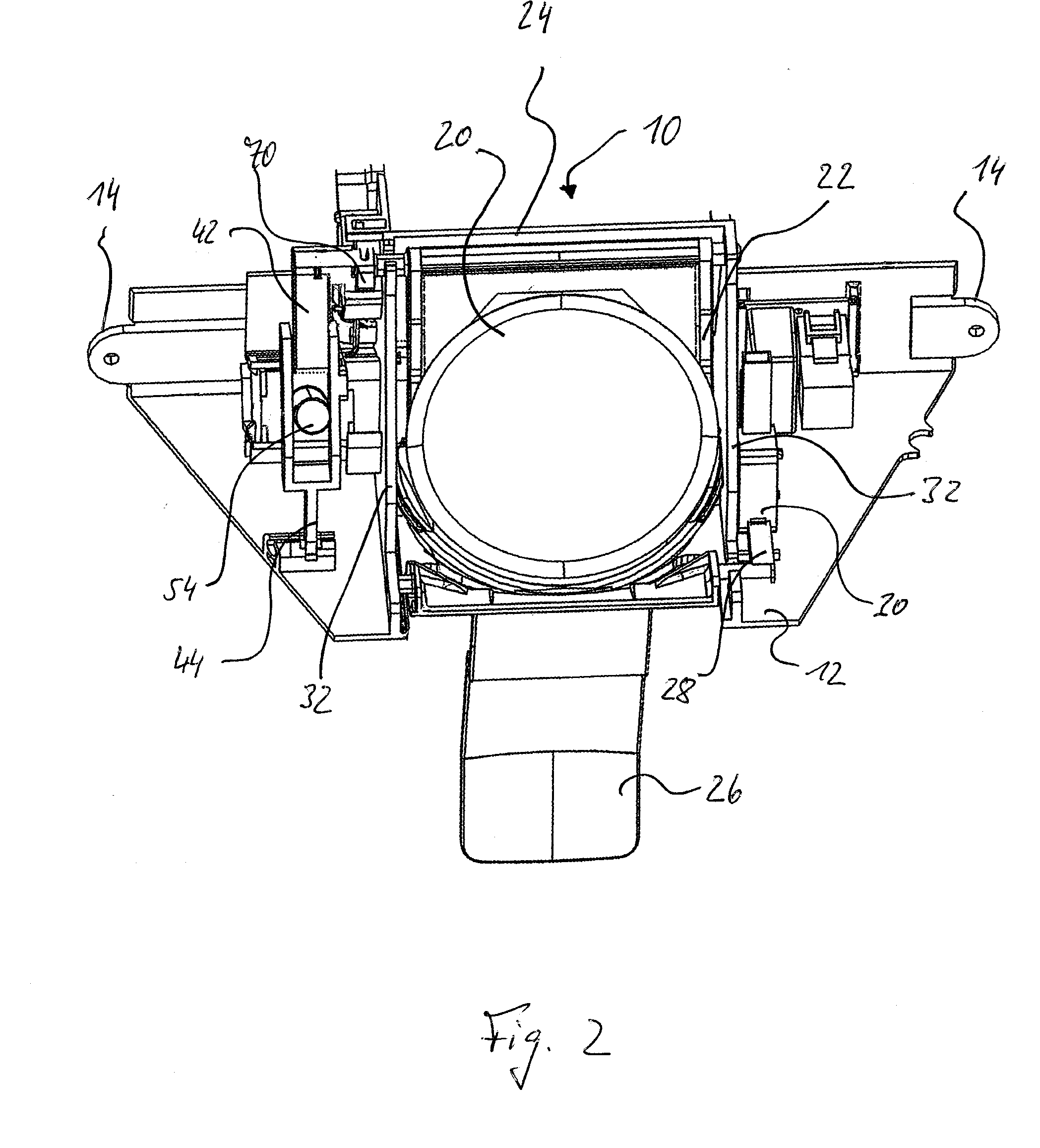
[0034]In order to explain the ice dispenser in accordance with the first embodiment, reference is first made to FIGS. 1 and 2. The ice dispenser illustrated in this instance, generally designated 10, has a dispenser housing 12 which is preferably made from plastics material and which is integrated in the door of a refrigerator in a manner not illustrated in greater detail. In order to install the ice dispenser 10, there are provided, inter alia, mounting straps 14 which are constructed on the dispenser housing 12 and which serve to secure the ice dispenser 10 to a retaining construction of the refrigerator by means of screws.

[0035]The dispenser housing 12 defines a mouth opening 16 (FIG. 1) of a dispenser shaft which is also not indicated in greater detail and in which ice is provided in cube form or in crushed form for dispensing through the mouth opening 16. When the ice dispenser is in the installed state, the mouth opening 16 is located above a dispensing compartment which is co...


PUM

PropertyMeasurementUnit
mechanical retentionaaaaaaaaaa
bias forceaaaaaaaaaa
movementaaaaaaaaaa

Abstract

The invention relates to an ice dispenser (10) for a refrigerator that includes a flap unit (24) which is arranged in an ice dispenser shaft and which can be adjusted between a release position which releases the ice dispenser shaft for dispensing ice and a locking position which blocks the ice dispenser shaft against dispensing ice, a pulse-controlled actuating magnet arrangement (58) for actuating the flap unit (24), and mechanical retention means (36, 64, 66) which releasably retain the flap unit (24) in the release position and in the locking position thereof, respectively.

Description

CROSS-REFERENCE TO RELATED APPLICATIONS[0001]This application claims the benefit of German Patent Application No. DE 10 2007 038 182.6, filed Aug. 13, 2007, in the German Patent Office.BACKGROUND OF THE INVENTION[0002]1. Field of the Invention[0003]The present invention relates to an ice dispenser for a refrigerator.[0004]2. Description of the Prior Art[0005]Refrigerators are known which have an integrated ice dispenser for dispensing ice cubes and / or crushed ice and often optionally also drinking water. The ice dispenser is generally located at the front of the refrigerator and is integrated in a door. It provides a slide-in compartment in which a glass can be placed which is intended to be filled with the ice or water. Above the glass, a dispensing shaft or channel terminates in which the ice is provided and which can be opened and closed by means of a flap.[0006]US 2006 / 0144075 A1 discloses an ice dispenser whose flap is opened and closed in an electromotive manner.[0007]Alternat...

Claims


Application Information

Patent Timeline
Patent Type & Authority Applications(United States)
IPC IPC(8): G07F11/00G07F9/10
CPCF25C5/005F25C5/22
Inventor DIRNBERGER, ALBERTSPIESSL, GEORG
Owner EMZ HANAUER
Learn More