Overcap for a spray device

a container and overcap technology, applied in the field of overcaps for containers, can solve the problems of difficult manufacturing, many of the actuator mechanisms are unusable, and cannot be easily used in a stand-alone manner and a hand, and the existing automated valve activation system for valves with tilt-activated valve stems is complex and cumbersom

Active Publication Date: 2009-02-19
SC JOHNSON & SON INC
View PDF99 Cites 33 Cited by
  • Summary
  • Abstract
  • Description
  • Claims
  • Application Information

AI Technical Summary

Problems solved by technology

Typically, these actuator mechanisms are unwieldy and are not readily adaptable to be used in a stand-alone manner and a hand-held manner.
Further, many of these actuator mechanisms exhibit a great deal of power consumption.
Existing automated valve activation systems for valves having tilt-activated valve stems are complex and may be difficult to manufacture.
Complex systems including gears, springs, and precise interactions of a multitude of moving parts may also be expensive to manufacture and too large to fit in an overcap for a container.
Complex systems may also require more power to operate and may have a greater tendency to break than systems of simpler construction.

Method used


Image

  • Overcap for a spray device
  • Overcap for a spray device
  • Overcap for a spray device

Examples


Embodiment Construction

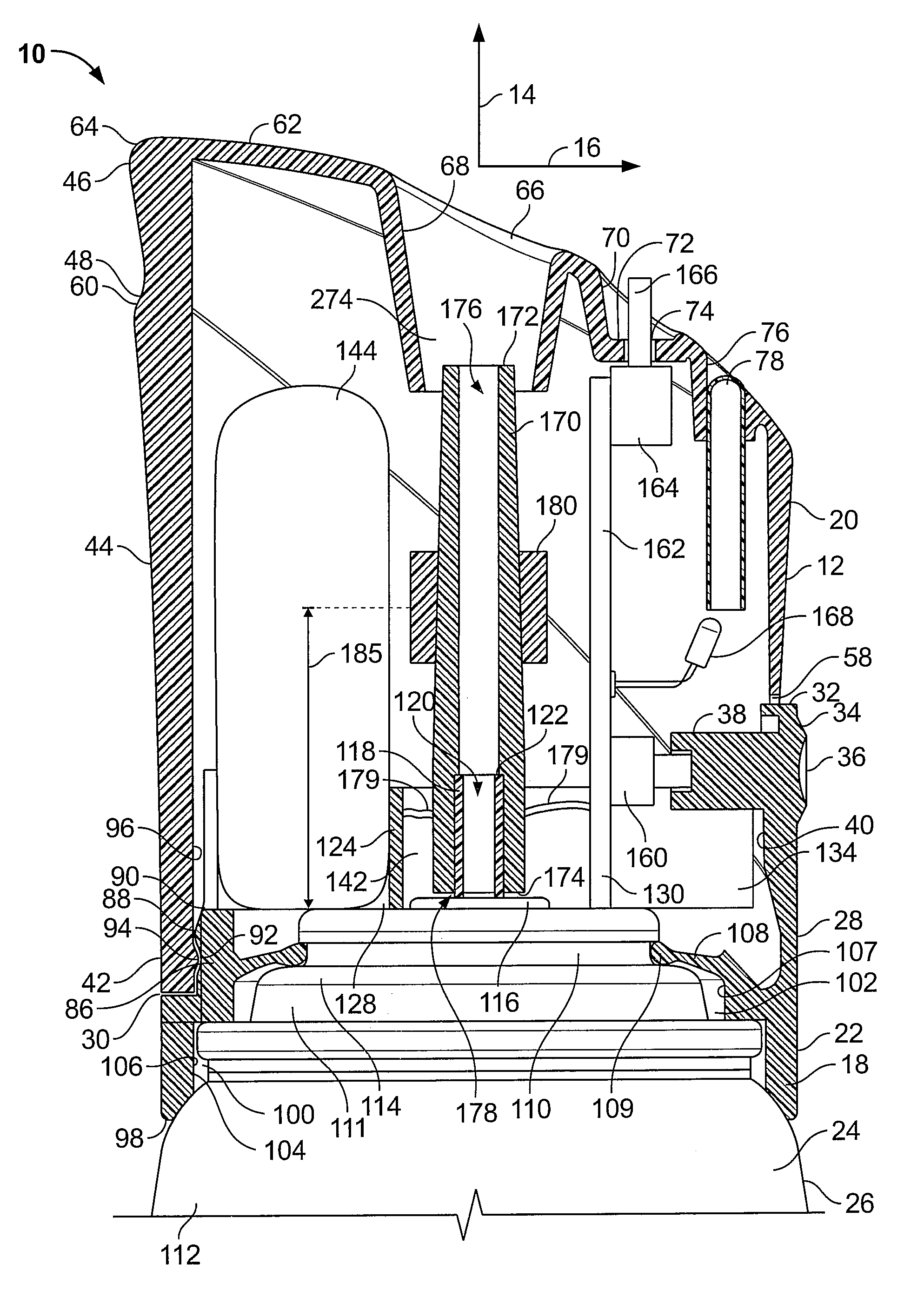
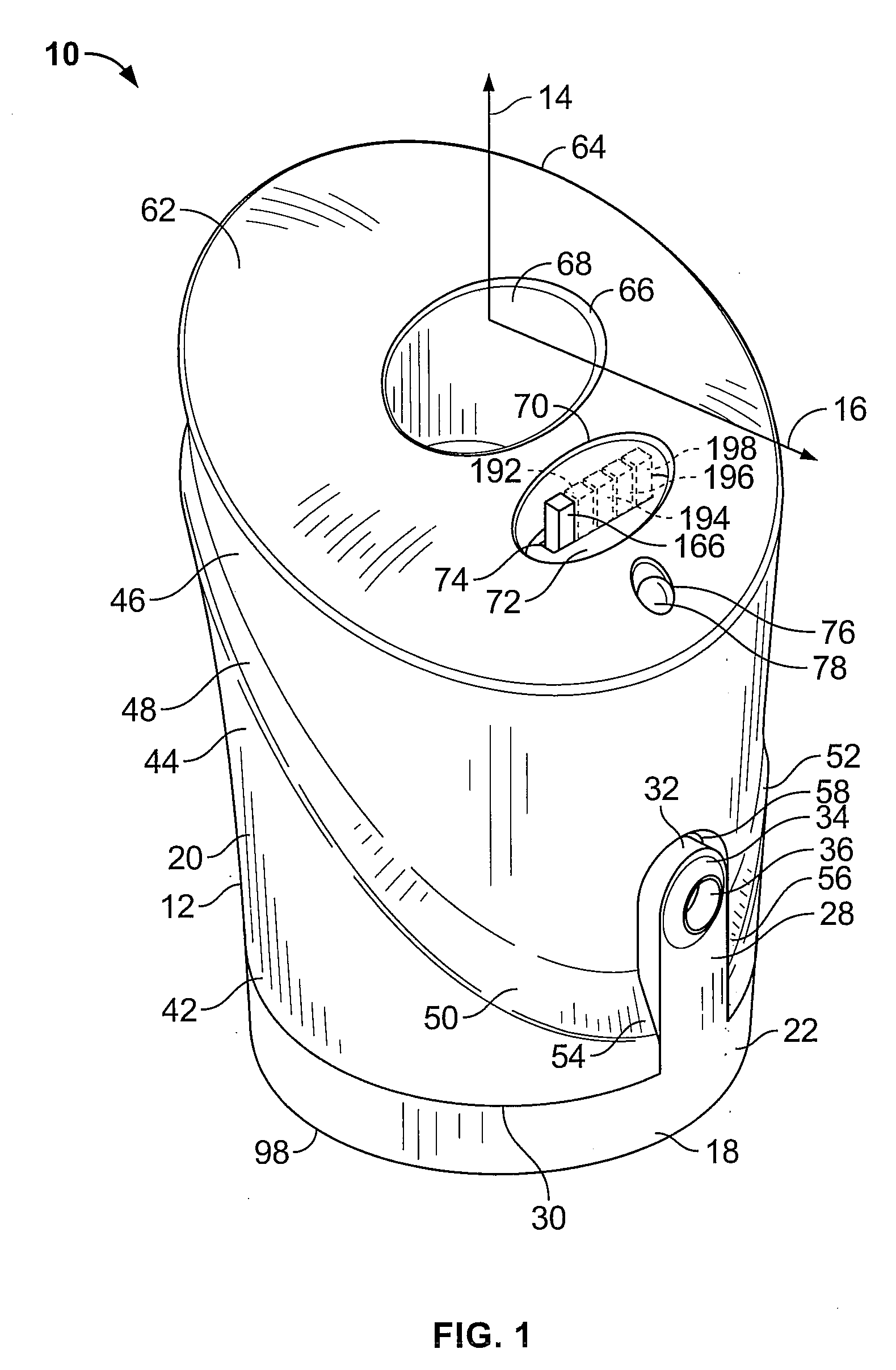
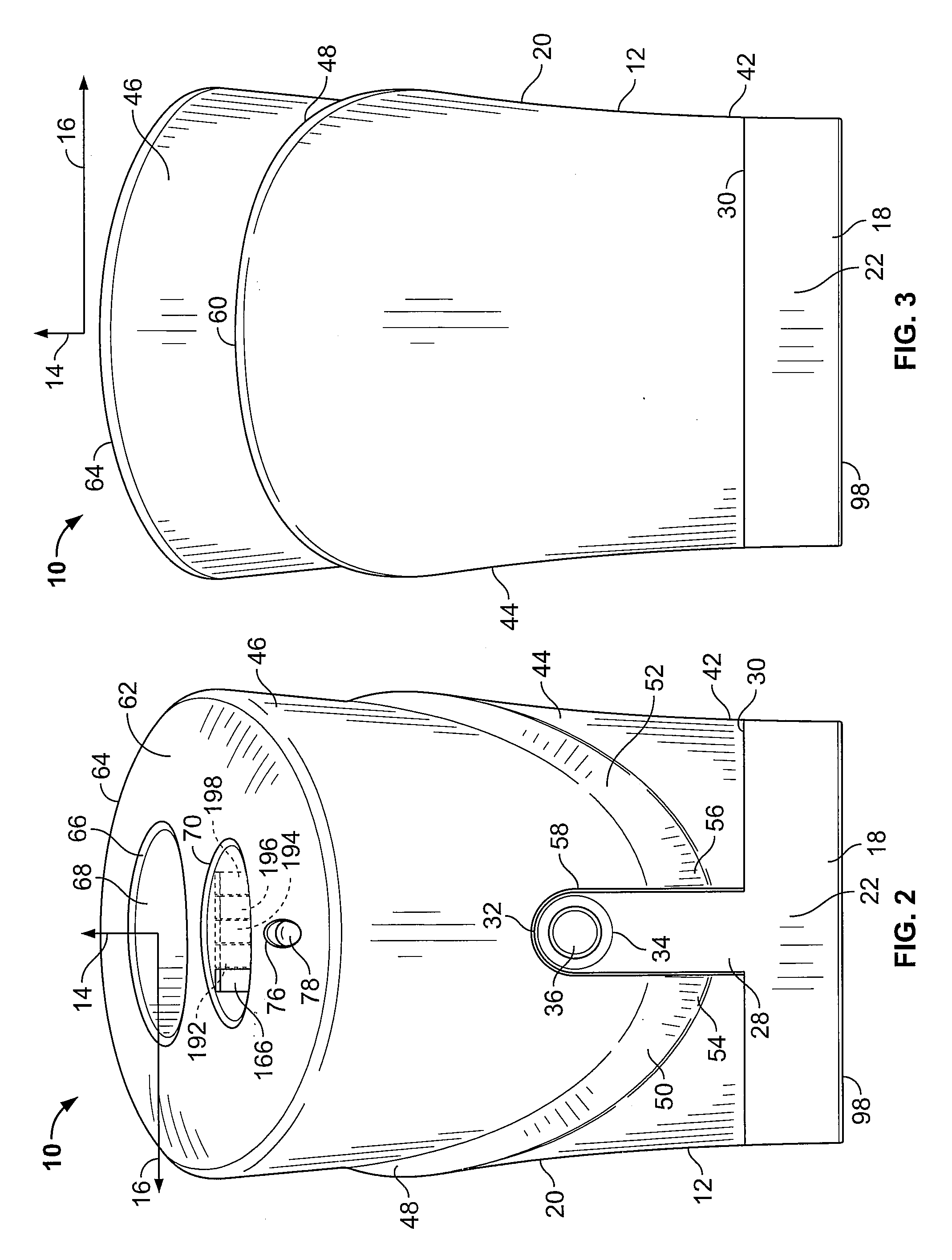
[0038]FIGS. 1-6 depict an actuator overcap 10 having a generally cylindrical housing 12 that has a longitudinal dimension along a longitudinal axis 14 and a radial dimension along a radial axis 16. The housing 12 includes a base portion 18 and a removable cap 20. The base portion 18 comprises a cylindrical section 22 adapted to be retained on an upper end 24 of a conventional aerosol container 26, which is shown in FIG. 7, and will be described in further detail below. A post 28 extends upwardly from a top end 30 of the cylindrical section 22. The post 28 includes a curved distal end 32 with an oval pushbutton 34 on an outer wall thereof. The pushbutton 34 is further provided with a concave depression 36. A cylindrical rod 38 (see FIG. 8) is provided on an inner wall 40 (see FIG. 9) of the post 28 generally opposite the pushbutton 34.

[0039]The removable cap 20 includes a cylindrical bottom portion 42, which has a diameter substantially equal to that of the top end 30 of the cylindri...


PUM


Abstract

A dispensing system includes a tilt-activated valve stem operably connected to a valve on a container and a vibe motor in communication with the valve stem. The vibe motor is adapted to impart radial motion to the valve stem upon activation.

Description

CROSS REFERENCE TO RELATED APPLICATIONS[0001]Not applicableREFERENCE REGARDING FEDERALLY SPONSORED RESEARCH OR DEVELOPMENT[0002]Not applicableSEQUENTIAL LISTING[0003]Not applicableBACKGROUND OF THE INVENTION[0004]1. Field of the Invention[0005]The present disclosure relates generally to an overcap for a container, and more particularly to an overcap adapted to be placed on an aerosol container having a tilt-activated valve stem.[0006]2. Description of the Background of the Invention[0007]Aerosol containers are commonly used to store and dispense volatile materials such as air fresheners, deodorants, insecticides, germicides, decongestants, perfumes, and the like. The volatile material is stored under compression and typically in a liquid state within a container. A release valve on the container controls release of the volatile material contained under compression therein. The release valve typically has a valve stem that outwardly extends from the valve, wherein the valve is activa...

Claims


Application Information

Patent Timeline
Patent Type & Authority Applications(United States)
IPC IPC(8): B67D5/08B65D83/00B67D3/00G04C23/42B67D7/08
CPCA61L9/14B65D83/46B65D83/262
Inventor HELF, THOMAS A.PAAS, EDWARD L.
Owner SC JOHNSON & SON INC
Why Eureka
Try Eureka