Device for Leakproof Connection of Telecommunication Cables and Production Method Thereof

Inactive Publication Date: 2009-02-19
FRANCE TELECOM SA
View PDF3 Cites 4 Cited by
  • Summary
  • Abstract
  • Description
  • Claims
  • Application Information

AI Technical Summary

Benefits of technology

[0016]The resin may be cast into the plug via an injection tube that opens out between the tubes. Under such circumstances, the tubes a

Problems solved by technology

Furthermore, the cable inlets of such boxes are bulky because they are constituted by tubular plugs that are leaktight and strong.
Not only do the cable inlets of that document fail to achieve cable densification th

Method used


Image

  • Device for Leakproof Connection of Telecommunication Cables and Production Method Thereof
  • Device for Leakproof Connection of Telecommunication Cables and Production Method Thereof
  • Device for Leakproof Connection of Telecommunication Cables and Production Method Thereof

Examples


Example

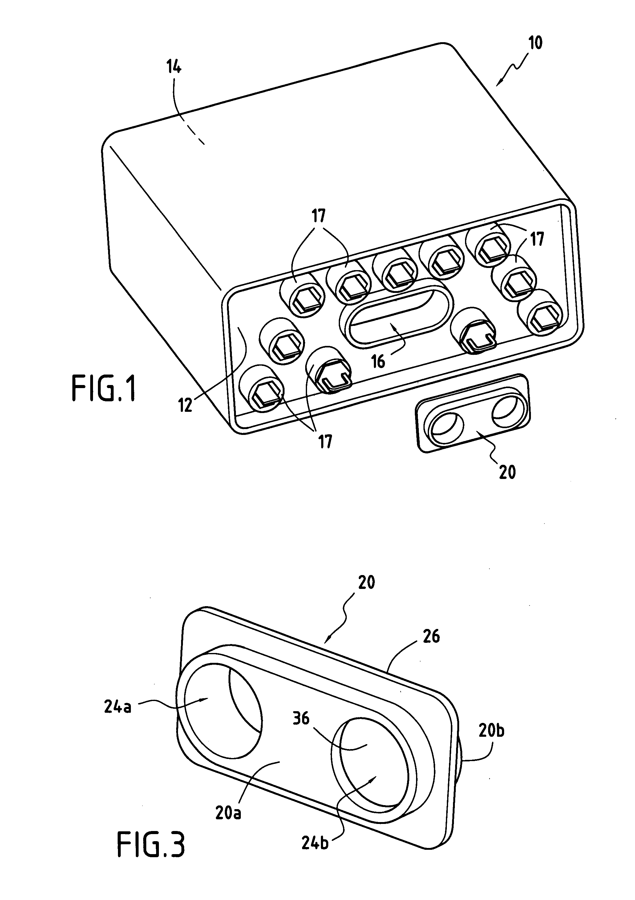
[0021]FIG. 1 is a diagrammatic view of a protective box 10 typically used in the terminal portion of a telecommunications network to serve a large number of users from a single point.

[0022]The box 10 is substantially in the form of a rectangular parallelepiped presenting at opposite ends an inlet face 12 and an outlet face 14. The inlet face 12 presents at least one inlet orifice 16 for passing optical fiber telecommunications cables.

[0023]Additional orifices 17 are also provided in the inlet face 12 of the box. These additional orifices 17 serve to enable single telecommunications cables to enter or leave the box.

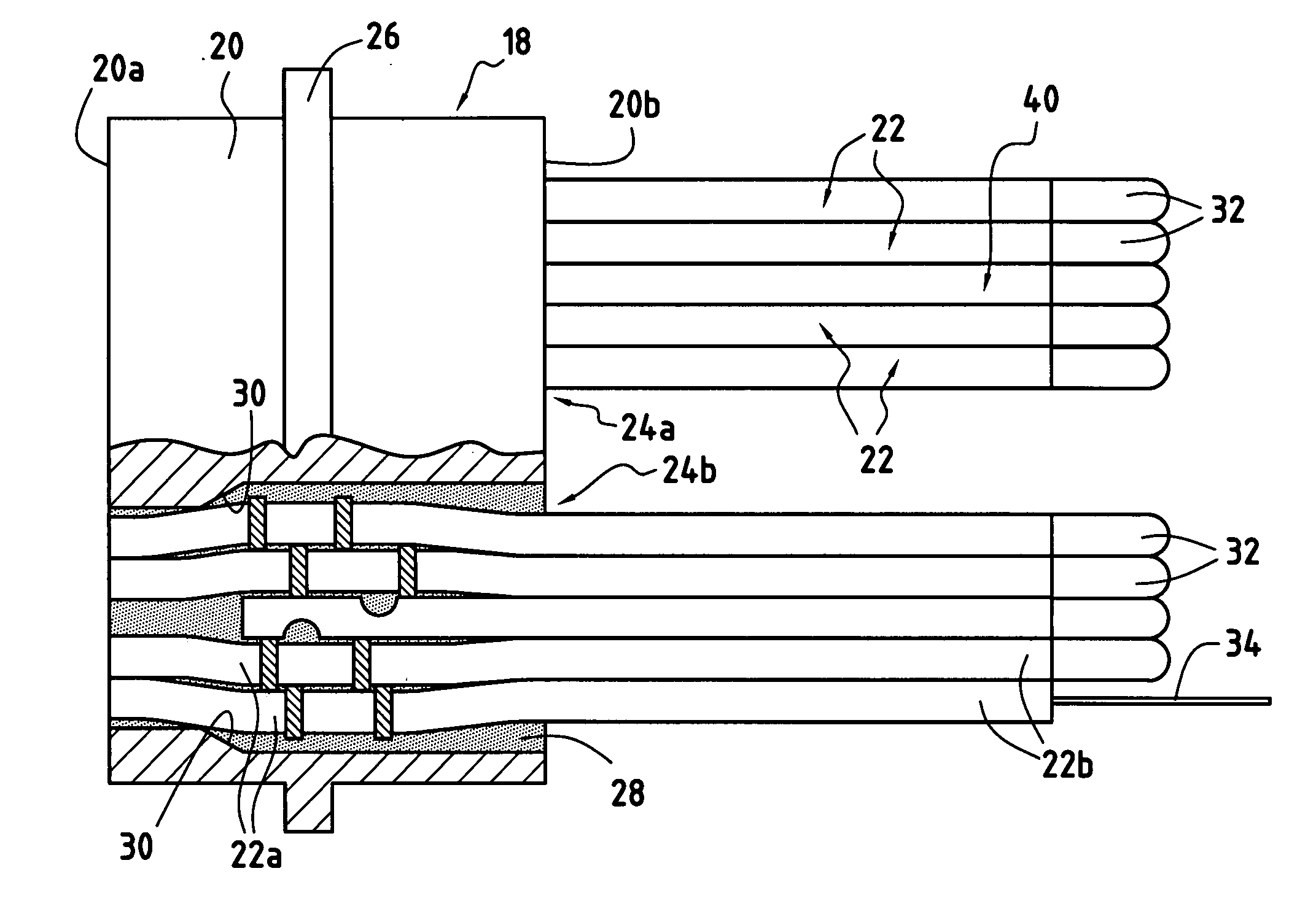
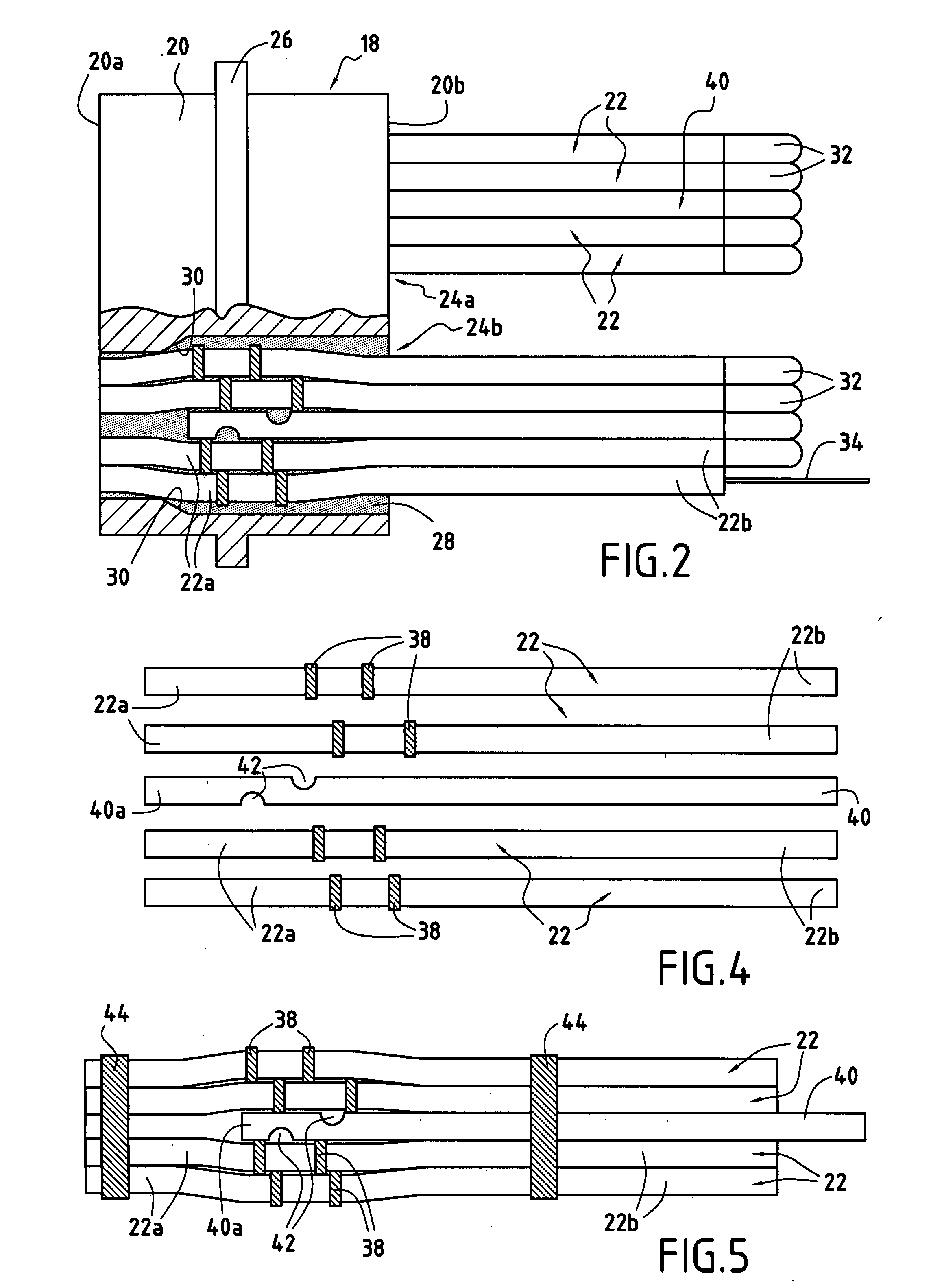
[0024]With reference to FIG. 2, a device 18 for sealed connection of telecommunications cables is designed to be housed in the inlet orifice 16 formed in the inlet face 12 of the box 10.

[0025]The connection device 18 of the invention comprises in particular a tubular plug 20 and a plurality of tubes 22 each serving to receive at least one telecommunications cable (also ref...


PUM


Abstract

A sealed connection device (18) for telecommunications cables comprises a tubular plug (20) for being received in an inlet of a protective box for telecommunications, with a plurality of tubes (22) each designed to receive at least one telecommunications cable (34). The tubes (22) are disposed longitudinally in the plug (20) so as to pass right through it, and a resin (28) is cast between the tubes (22) so as to provide both mechanical retention of the tubes in the plug and sealing of the connection device.

Description

BACKGROUND OF THE INVENTION[0001]The present invention relates to the general field of telecommunications. It relates more particularly to a device for sealed connection of telecommunications cables, for example optical fibers, the device being for use in a protective box used for distribution lines.[0002]The optical fiber cables that are used to construct telecommunications lines are connected by means of connectors and splices. In order to protect them from moisture and other ambient agents (oils, acids, or other pollutants), cable ends and connectors are generally placed in sealed protective boxes which are themselves placed in telecommunications structures (underground chambers, cabinets, raceways, etc.).[0003]Such protective boxes, which are generally tubular or parallelepipedal in shape, present inlets that are usually situated in two opposite faces. These inlets need to be thoroughly sealed, both with respect to their own closure devices and with respect to their cable inlets...

Claims


Application Information

Patent Timeline
IPC IPC(8): H02G15/013F16C1/26
CPCG02B6/4471Y10T403/475H02G15/04H02G15/013H02G15/10
Inventor CAILLEAUX, JEAN-MARCCAHUZAC, BERNARD
Owner FRANCE TELECOM SA
Why Eureka
Try Eureka