
Print architecture for driving multiple print heads

a print head and print technology, applied in the field of computer software, can solve the problems of additional memory requirements and high implementation costs, and achieve the effect of enhancing the throughput of the print system and reducing the processing time associated

Inactive Publication Date: 2009-02-19
PITNEY BOWES INC
View PDF3 Cites 4 Cited by
  • Summary
  • Abstract
  • Description
  • Claims
  • Application Information

AI Technical Summary

Benefits of technology

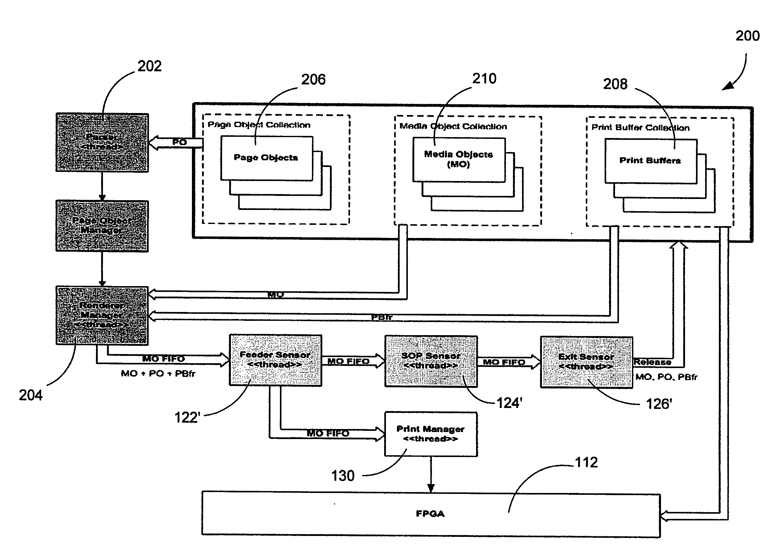
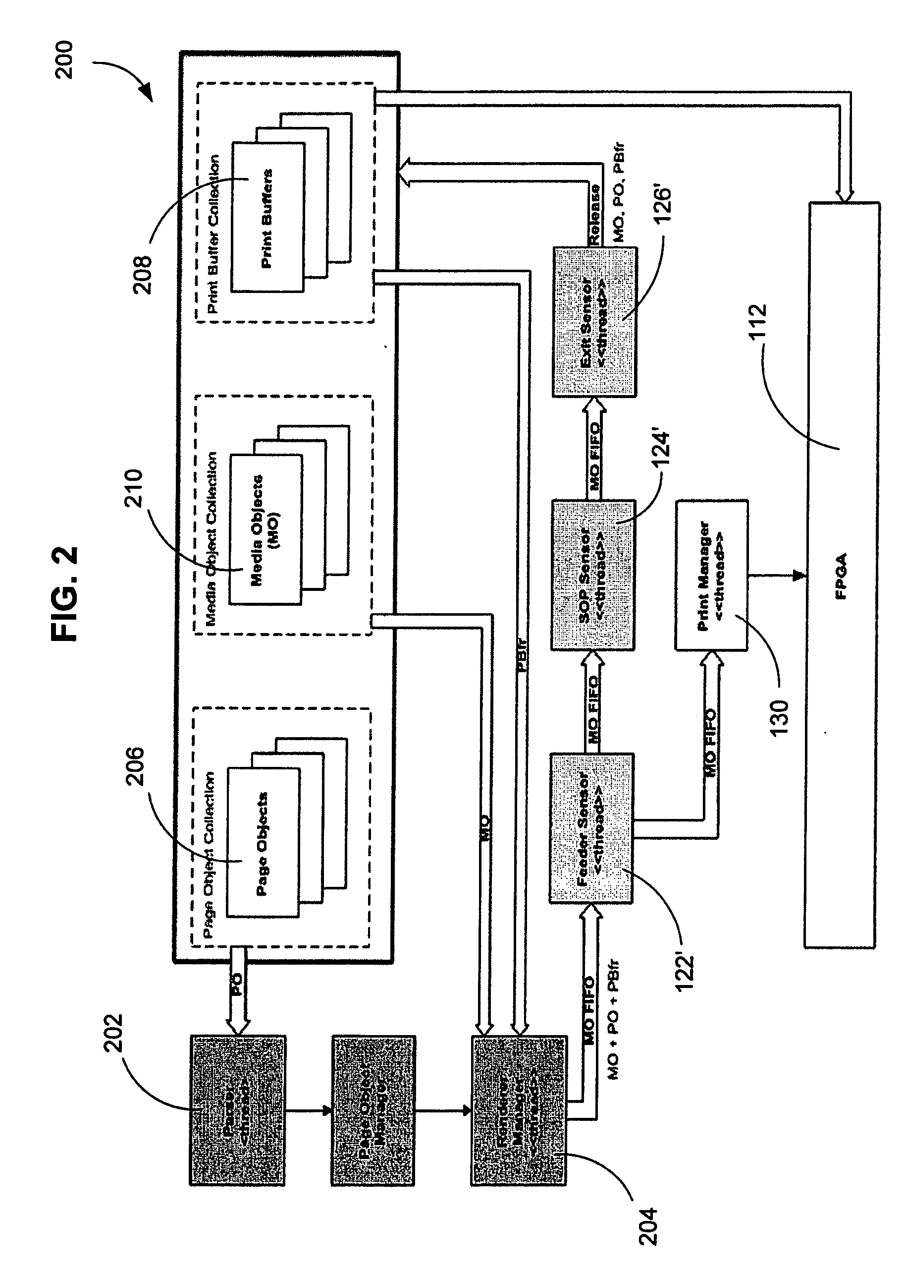
[0006]A system architecture is provided for a fixed-head mailpiece printer. The printer includes at least two laterally and longitudinally-spaced print heads for depositing ink on a face surface of a mailpiece. The print system architecture includes print application software or software program code operative to render print image data into a plurality of logical rectangular bitmap print buffers. Further, a field programmable gate array (FPGA) remaps each of the logical rectangular bitmap print buffers into one of the print heads based upon its spatial position relative to the mailpiece. Furthermore, the FPGA is operative to control the deposition of ink from the print heads based upon the print image data contained in the print buffers. Moreover, the FPGA minimizes processing time associated with print image rendering to achieve enhanced print system throughput.

Problems solved by technology

This configuration introduces additional memory requirements and is costly to implement, both from a hardware and software perspective.

Method used


Image

  • Print architecture for driving multiple print heads
  • Print architecture for driving multiple print heads
  • Print architecture for driving multiple print heads

Examples


Embodiment Construction

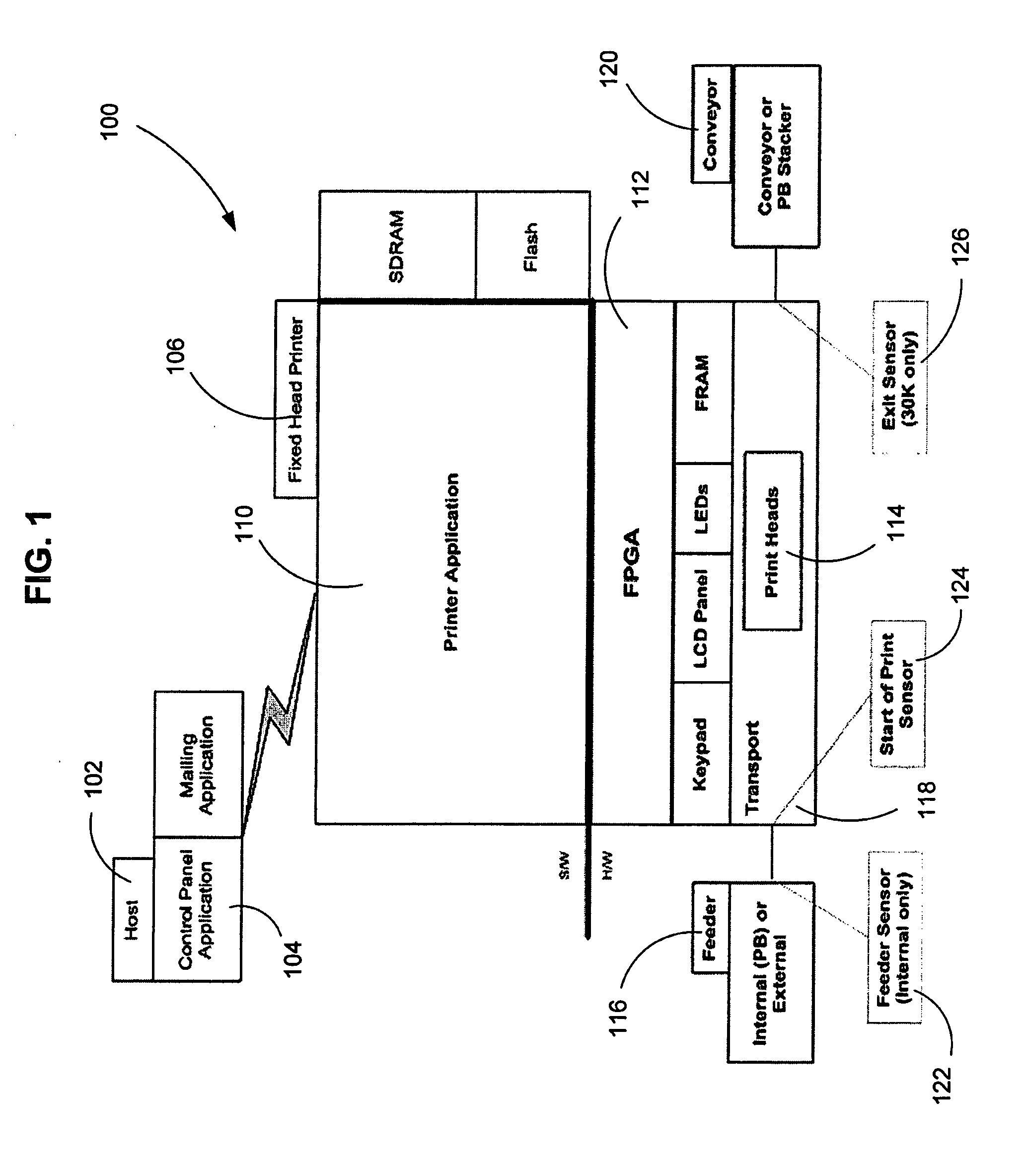
[0012]The inventive print system architecture and control algorithms therefor are described in the context of a fixed-head printer having two (2) banks of three print heads, though the inventive system architecture may be used in combination with any fixed head printer having at least two (2) longitudinally and / or laterally-spaced print heads.

[0013]The system architecture is operative to control a fixed-head mailpiece printer having laterally and longitudinally-spaced print heads. The print heads deposit ink on a face surface of the mailpiece in zones or regions of print. For example, one zone nearest the top edge of the mailpiece envelope may print a portion of the return address, a two-dimensional bar code image and a portion of the postage indicia for mailpiece delivery. A second zone, immediately below the first zone, may include the remainder of the return address, postage indicia and a portion of the destination address. Finally, a third zone, immediately below the second zone...


PUM


Abstract

A system architecture is provided for a fixed-head mailpiece printer. The printer includes at least two laterally and longitudinally-spaced print heads for depositing ink on a face surface of a mailpiece. The print system architecture includes print application software or software program code operative to render print image data into a plurality of logical rectangular bitmap print buffers. Further, a field programmable gate array (FPGA) remaps each of the logical rectangular bitmap print buffers into one of the print heads based upon its spatial position relative to the mailpiece. Furthermore, the FPGA is operative to control the deposition of ink from the print heads based upon the print image data contained in the print buffers. Moreover, the FPGA minimizes processing time associated with print image rendering to achieve enhanced print system throughput.

Description

CROSS REFERENCE TO RELATED APPLICATIONS[0001]This application claims priority under 35 USC §119(3) from Provisional Patent Application Ser. No. 60 / 955,900, filed Aug. 15, 2007, entitled PRINT ARCHITECTURE FOR DRIVING MULTIPLE PRINT HEADS (Attorney Docket Number G-359), which is incorporated herein by reference in its entirety.TECHNICAL FIELD[0002]The present invention relates to computer software for controlling the deposition of ink through print head nozzles, and more particularly, to a new and useful print architecture for driving multiple print heads.BACKGROUND OF THE INVENTION[0003]In-line printers for mailpiece creation, i.e., the printing of a destination address, return address and postage indicia, typically employ multiple print heads to print along dedicated “zones” on the face of a mailpiece envelope. Commonly, a plurality of microprocessors are employed, i.e., one for each print head, to control the deposition of ink from each of the print head nozzles. This configuratio...

Claims


Application Information

Patent Timeline
Patent Type & Authority Applications(United States)
IPC IPC(8): B41J29/38
CPCB41J3/543G07B2017/00524G07B17/00508
Inventor DAVIES, BRAD L.CRISTIANI, ELAINE B.SMITH, KEITH M.KIRSCHNER, WESLEY A.
Owner PITNEY BOWES INC
Learn More