Vacuum processing apparatus

a technology of vacuum processing and vacuum chamber, which is applied in the direction of pile separation, transportation and packaging, instruments, etc., can solve the problems of reducing the number of wafers to be processed per unit time to a great extent, causing waiting time, and not considering enough adjustment, so as to improve the throughput

Active Publication Date: 2014-05-20
HITACHI HIGH-TECH CORP
View PDF7 Cites 2 Cited by
  • Summary
  • Abstract
  • Description
  • Claims
  • Application Information

AI Technical Summary

Benefits of technology

[0014]An object of the present invention is to provide a vacuum processing apparatus capable of improving the throughput.
[0026]Furthermore, the controller uses precedently stored information concerning times of individual operations covering take-out of the sample from the cassette, process of the sample in the processing chamber and thereafter return of the sample to the cassette so as to carry out the cummulation for a plurality of kinds of schedules in which the order of these operations and the stagnation time are made to be different and from the plurality of kinds of schedules, selects as operation schedule information an operation which minimizes the total process time for processing a given number of the samples.

Problems solved by technology

The above related arts fail to consider the following points sufficiently, raising problems.
Accordingly, if the sequence of operations in the transfer unit is determined such that wafers now being ready for transfer are sequentially transferred, in the case of simultaneous establishment of preparation for transfer in a plurality of processing chambers or parallel establishment of preparation for transfer in another processing chamber on the way of transfer of another wafer, a plurality of transferable wafers are sequentially transferred by first finishing transfer in one processing chamber and thereafter shifting to transfer in the other processing chamber by pausing transfer on the way of operation and then shifting to the next transfer operation, with the result that a waiting time is caused to occur in at least one processing chamber, amounting up to a transfer time required for one wafer transfer at the most.
The related art does not consider sufficiently adjustment of the timing of occurrence of waiting time, failing to take into account a problem that the waiting time occurs unexpectedly and is cumulated, thus reducing the number of wafers to be processed per unit time to a great extent.

Method used


Image

  • Vacuum processing apparatus
  • Vacuum processing apparatus
  • Vacuum processing apparatus

Examples


Embodiment Construction

[0037]Embodiments of the present invention will now be described with reference to the accompanying drawings.

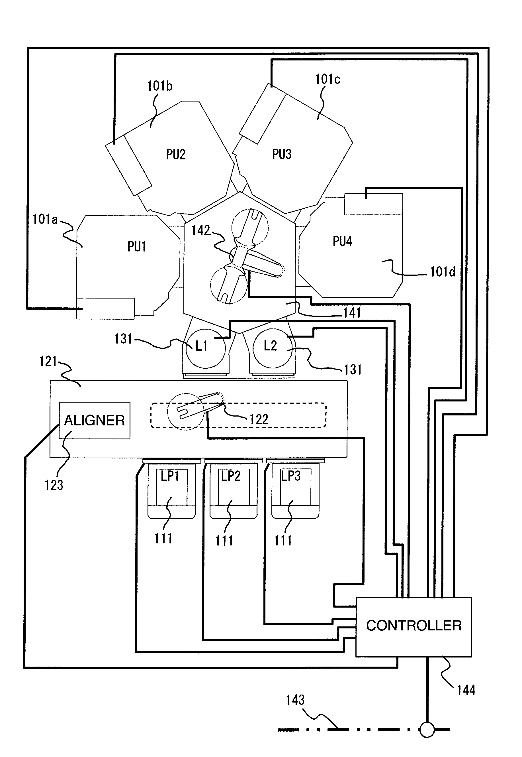
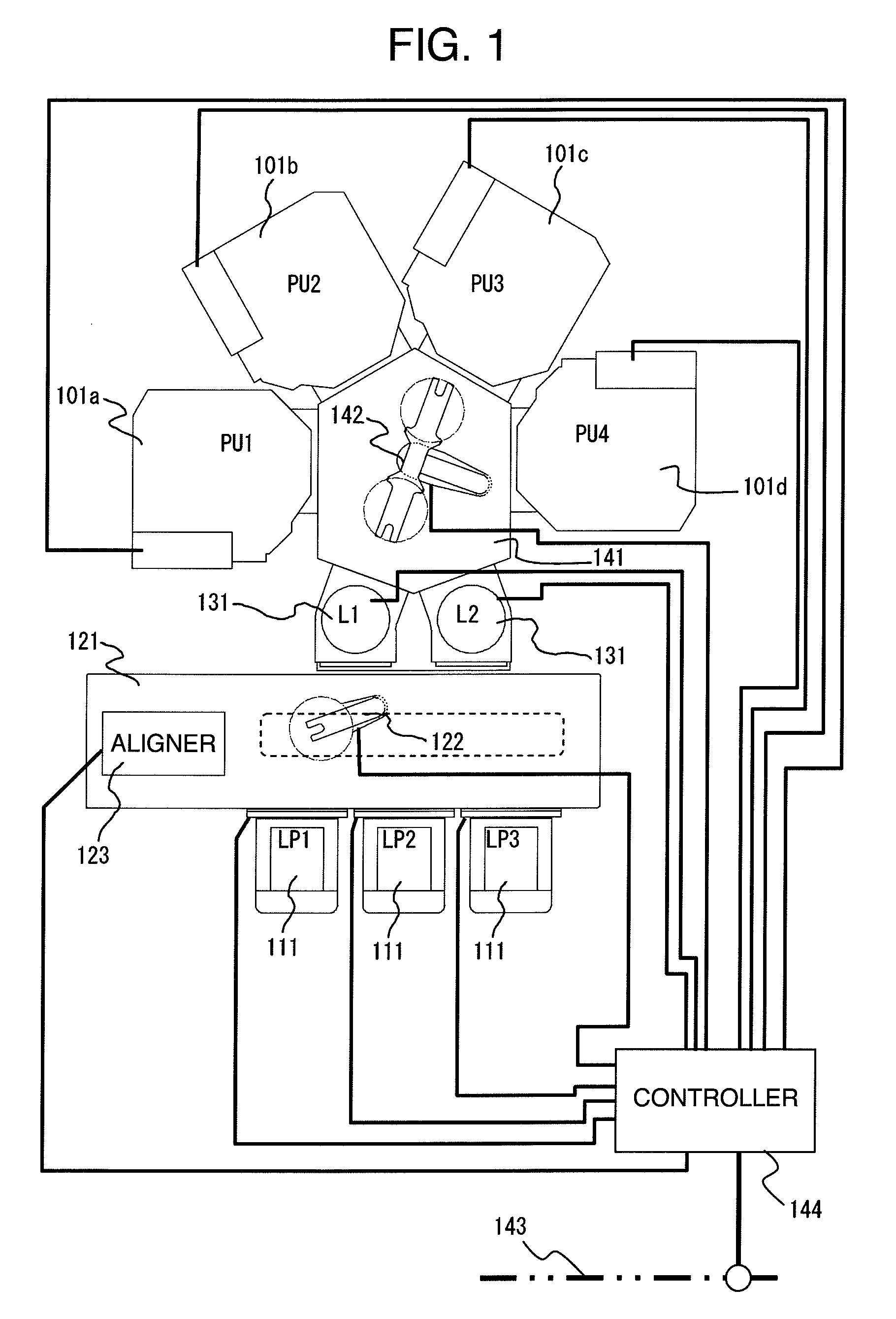
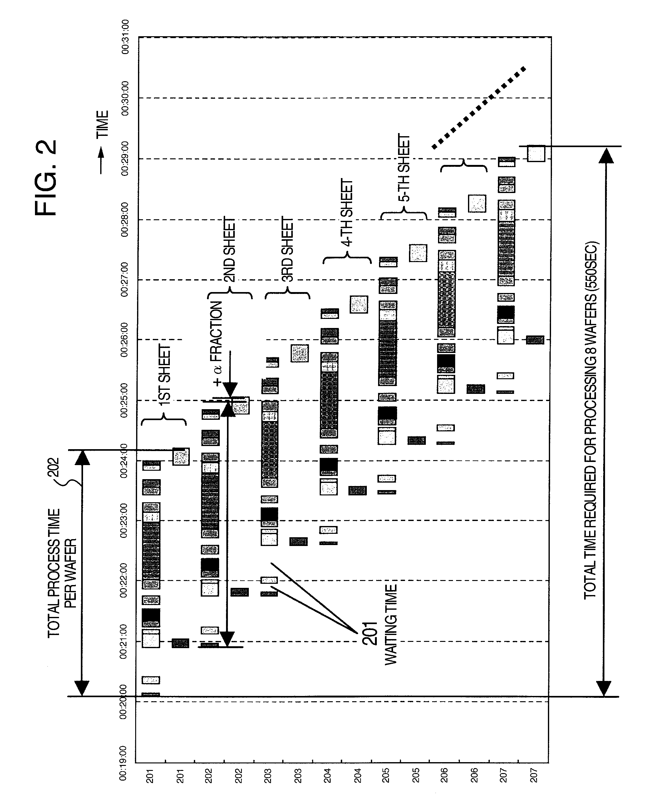
[0038]The present invention intends to improve the throughput in the transfer rate-controlling region and in the case of the process time in a processing chamber (process unit) being sufficiently short, by scheduling in advance all steps associated with processing a sheet of wafer, the stable throughput can be realized which does not depend on timings of individual processes / individual operations. In a multi-chamber system generally called a cluster tool in which a plurality of processing chambers (process units) are provided for a single transfer system, there is a region in which the throughput is determined by operation of the transfer system (time required for transfer) if the process time in the pressing chamber is sufficiently short. This is due to such a phenomenon that because of the short processing time, the throughput of the plural processing chambers per unit time...


PUM


Abstract

A vacuum processing apparatus includes a plurality of vacuum containers; a vacuumized transfer unit connected with the vacuum containers and having a transfer chamber; a plurality of lock chambers connected to the vacuumized transfer unit; a vacuumized transferring section arranged in the transfer chamber to transfer the sample between each of the lock chambers and each of the processing chambers inside the plurality of vacuum containers; an atmospheric transfer container having a space through which the sample is transferred under the atmospheric pressure; an atmospheric transfer unit arranged in the atmospheric transfer container and adapted to transfer the sample from a cassette; and a controller operative on the basis of schedule information of a plurality of operations to adjust the operations, the information including times of stagnation of the plurality of samples and set therefor.

Description

BACKGROUND OF THE INVENTION[0001]The present invention relates to a vacuum processing apparatus for processing an objective, for example, a substrate-like sample such as a semiconductor wafer in a processing chamber inside a vacuum container and more particularly, to a vacuum processing apparatus having a plurality of vacuum containers (process units) provided for a transfer system unit, generally called a cluster tool, thus having the ability to process a plurality of wafers to improve the productivity.[0002]A semiconductor production apparatus for producing a semiconductor device by processing a semiconductor wafer as above is provided with a plurality of process units each having a vacuum container with an internal processing chamber called a process unit, a vacuum evacuation unit and a plasma generation unit and is used to process a substrate-like sample such as a semiconductor wafer (hereinafter referred to as a wafer) by using a plasma generated in the processing chamber. In t...

Claims


Application Information

Patent Timeline
Patent Type & Authority Patents(United States)
IPC IPC(8): H01L21/67
CPCH01L21/67778H01L21/67745
Inventor KIMURA, SHINGOOKIGUCHI, SHOUJIKAGOSHIMA, AKIRAOBAMA, SHINJI
Owner HITACHI HIGH-TECH CORP
Why Eureka
Try Eureka