Protection structure for heat dispersing device of power supplier

a technology of heat dispersing device and protection structure, which is applied in the direction of electrical apparatus casing/cabinet/drawer, cooling/ventilation/heating modification, instruments, etc., can solve the problems of electricity leakage or short circuit, air leakage, electricity leakage or other problems, and the problem of improving the heat dispersing structure of the power supplier has already become a significant issu

Inactive Publication Date: 2009-02-19
SPI ELECTRONICS +1
View PDF9 Cites 4 Cited by
  • Summary
  • Abstract
  • Description
  • Claims
  • Application Information

AI Technical Summary

Benefits of technology

[0004]The object of the present invention is to inhibit the electromagnetic interference, to entirely control the direction of air flow and protect the wiring of the heat dispersing device.

Problems solved by technology

However, owing to the high operation efficiency of current electronic elements (which represents of high thermal energy), the fan with the height less than 38 mm can not sufficiently disperse the heat, so that the heat energy will accumulate inside the case.
However, since the above described fan for the power supplier is assembled with the metal case through the breakout opening, an air leakage might occur at the gap between the opening and the fan, and the electromagnetic wave might also leak out through the gap so as to cause an electromagnetic interference.
Further, the power cord of the fan is exposed to the outside owing to the breakout opening, so that the wiring is easily damaged thereby causing electricity leakage or short circuit.
Therefore, how to improve the heat dispersing structure for power supplier has already become a significant issue.

Method used


Image

  • Protection structure for heat dispersing device of power supplier
  • Protection structure for heat dispersing device of power supplier
  • Protection structure for heat dispersing device of power supplier

Examples


Embodiment Construction

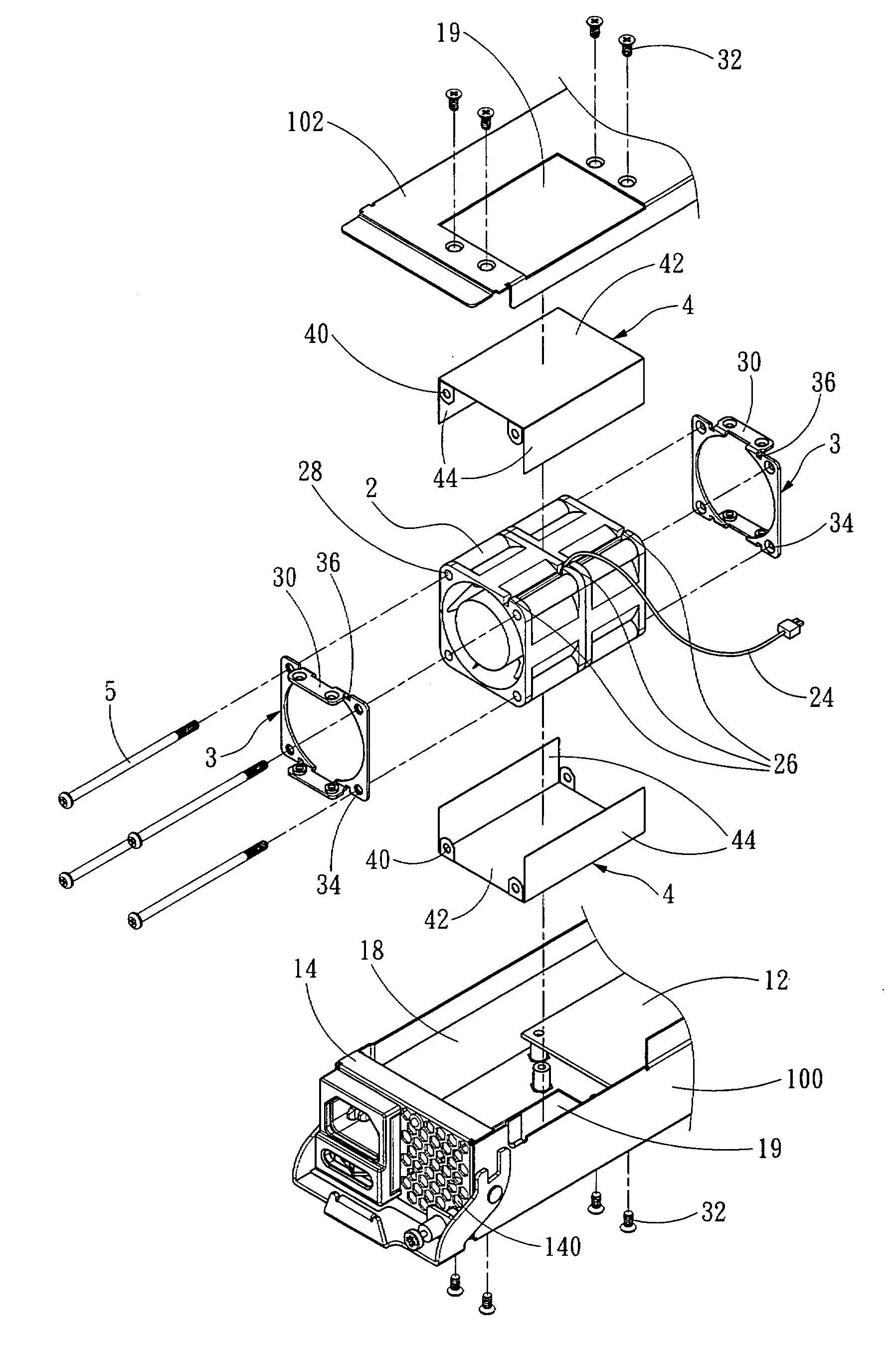
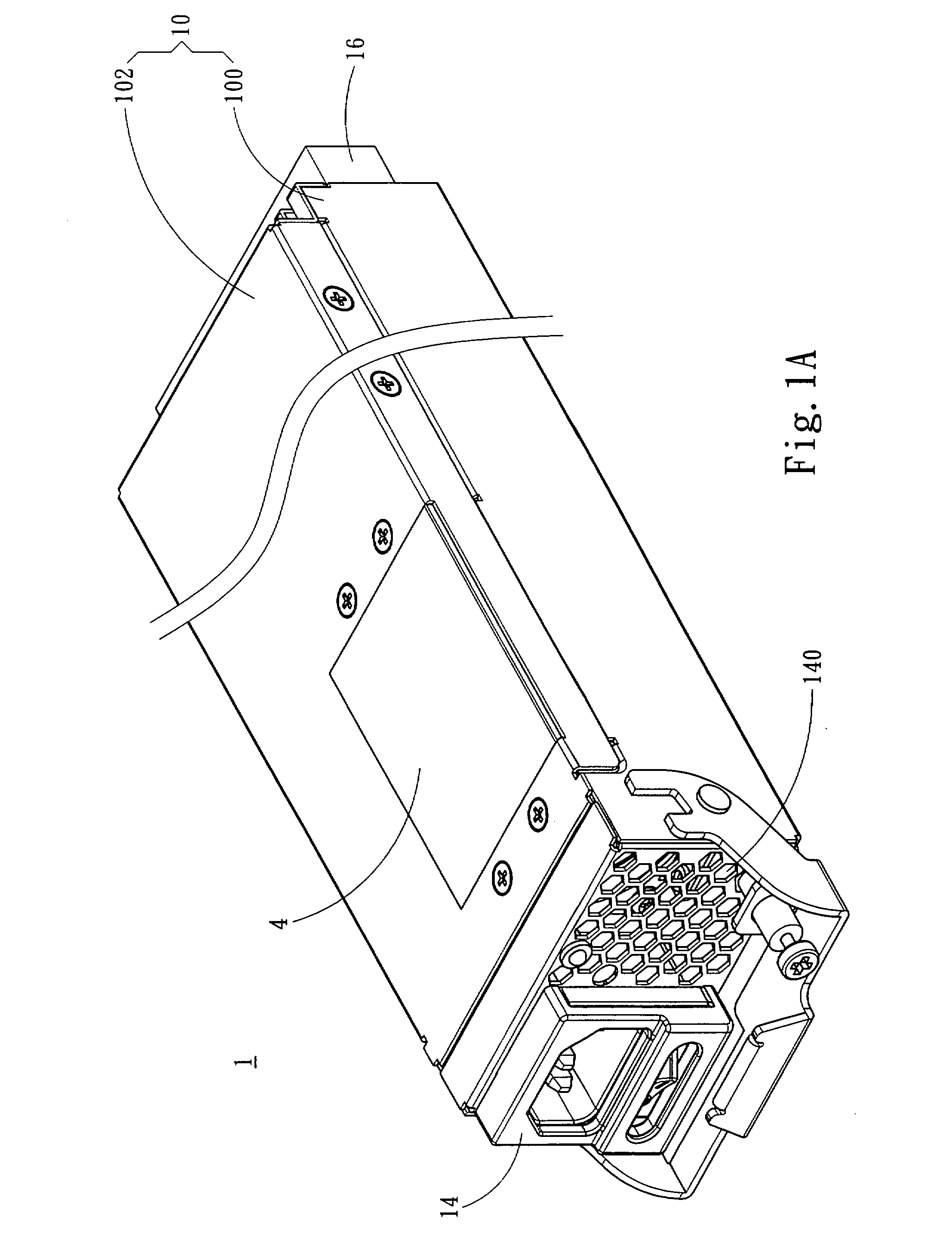
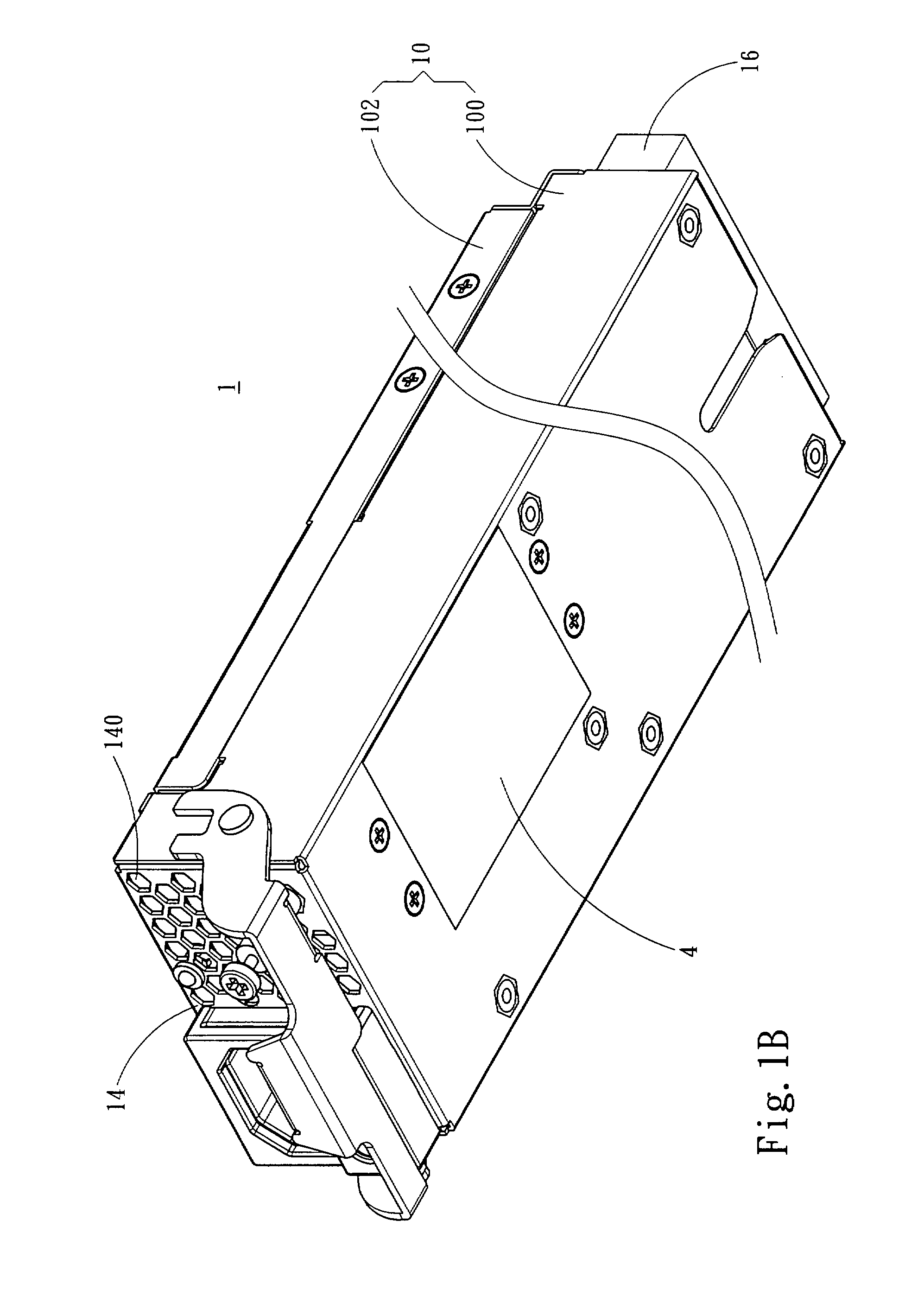
[0013]Please refer to FIG. 1A to FIG. 5, which are respectively a three-dimensional view, another three-dimensional view, a decomposition drawing, a schematic view showing the wiring arrangement, a schematic view showing the locking relationship and a sectional view of a preferred embodiment according to the present invention. As shown, the present invention provides a protection structure for a heat dispersing device of a power supplier. The power supplier 1 includes a metal housing 10, which includes a base 100 and a cover 102 covered on the base 100, a power input end 14 with plural vent holes 140, a power output end 16 and an accommodating space 18 inside the power supplier 1 between the power input end 14 and the power output end 16. The accommodating space 18 has a power processing unit 12 (such as, data access device, or circuit board) mounted therein, and the output terminal of the power processing unit 12 is located at the power output end 16 of the power supplier 1. Beside...


PUM


Abstract

The present invention includes a metal housing, a power input end, a power output end, and an accommodating space thereinside between the power input end and the power output end, the accommodating space has a power processing unit mounted inside and the output terminal of the power processing unit is located at the power output end of the power supplier. The metal housing of the power supplier has an assembling opening mounted thereon and located above the accommodating space for assembling at least a heat dispersing device. The protection structure includes a fixing frame, mounted in the accommodating space and fixedly connected with two sides of the heat dispersing device and the metal housing, and a metal protection case, covered on the assembling opening and tightly engaged with the metal housing, wherein the metal protection case and the fixing frame respectively have positioning portions corresponding to each other.

Description

FIELD OF THE INVENTION[0001]The present invention is related to a protection structure for a heat dispersing device, and more particularly, a protection structure for a heat dispersing device which can prevent air leakage and electromagnetic wave leakage from a power supplier.BACKGROUND OF THE INVENTION[0002]Cases for industrial computer, according to the height thereof, can be divided into different standards, 1U, 2U, 3U and 4U, wherein the case of standard 1U is limited to be 40 mm height with a case thickness of 1 mm, so that the fan installed inside the case must be limited to have a height less than 38 mm. However, owing to the high operation efficiency of current electronic elements (which represents of high thermal energy), the fan with the height less than 38 mm can not sufficiently disperse the heat, so that the heat energy will accumulate inside the case. Therefore, a heat dispersing structure for the power supplier is developed, as disclosed in R.O.C. Patent Publication N...

Claims


Application Information

Patent Timeline
Patent Type & Authority Applications(United States)
IPC IPC(8): H05K7/20H05K5/00
CPCG06F1/20G06F1/183
Inventor LU, SHAO-FENG
Owner SPI ELECTRONICS
Why Eureka
Try Eureka