Heat transfer apparatus

Inactive Publication Date: 2009-02-19
DIGITAL PROJECTION
View PDF31 Cites 22 Cited by
  • Summary
  • Abstract
  • Description
  • Claims
  • Application Information

AI Technical Summary

Benefits of technology

[0012]Viewed from a first aspect, the present invention relates to apparatus for cooling a light valve device, the apparatus comprising an array of elongate members, the elongate members each having a tip for contacting the light valve device. At least in preferred embodiments, the apparatus may allow the light valve device to be cooled without impairing its functionality. In use, the tips

Problems solved by technology

Because of the costs involved in producing Cinema film prints for distribution, together with the fact that motion picture film is easily damaged, other technologies were investigated in which the film or picture and sound information was stored digitally.
The brightness of image, which is important to po

Method used


Image

  • Heat transfer apparatus
  • Heat transfer apparatus
  • Heat transfer apparatus

Examples


Embodiment Construction

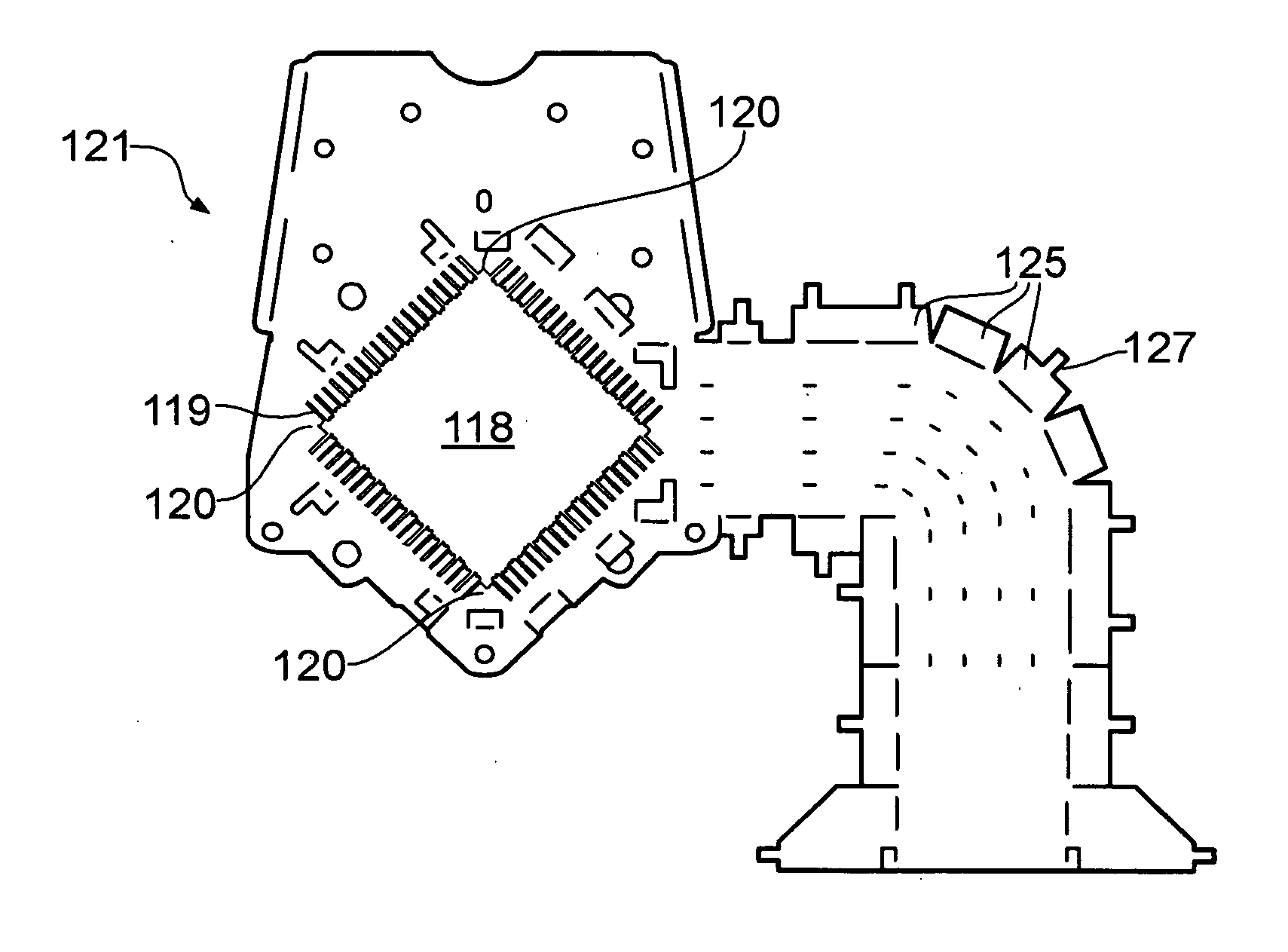
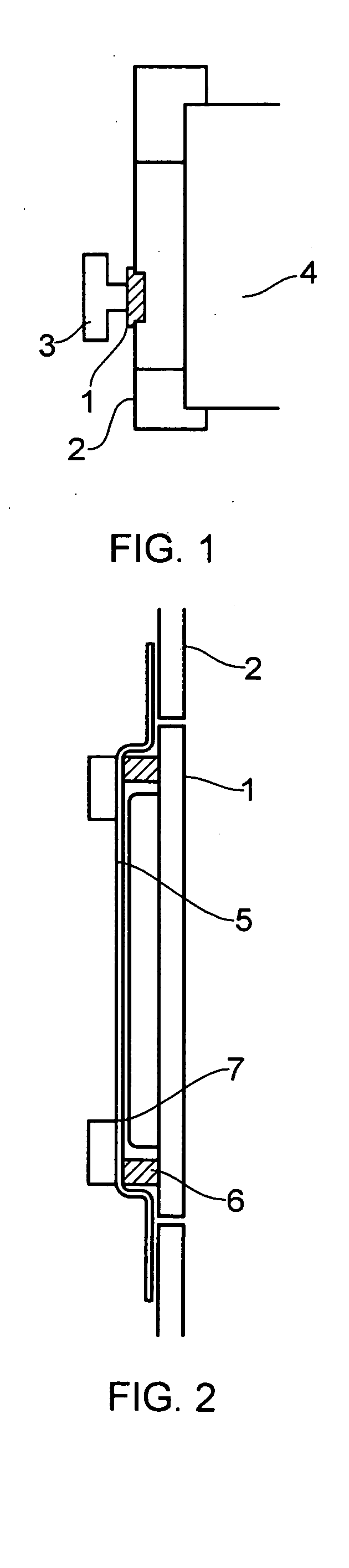
[0062]A prior art mounting assembly for a digital micro-mirror device (DMD) 1 in a conventional projection system is illustrated in FIG. 1. The DMD 1 is mounted on a plate 2 and a stud 3 is provided on a back face thereof to help conduct heat away from a DMD heatsink. The DMD 1 is proximal a prism 4, necessary for combining the Red, Green, and Blue light into the output beam.

[0063]The DMD 1 is packaged in such a way to exclude dust. This is particularly important at a 10.8 micrometer pitch since a given size of dust particle appears approximately 80% bigger on a projection screen than for a 17 micrometer pitch. Thus dust which may not have been objectionable with older chips is now unacceptable. To avoid dust settling on DMDs, they may be packaged in a hermetic enclosure with a window and this is arranged into a sealed enclosure typically formed using gaskets.

[0064]Conventional DMD packaging also comprises a light shield 5. This light shield is primarily to prevent light other than ...


PUM


Abstract

The present application relates to apparatus (100) for cooling a light valve device (103), the apparatus comprising an array of elongate members (119), the elongate members (119) each having a tip (131) for contacting the light valve device (103). The apparatus (100) is suitable for cooling a digital micro-mirror device (103). A duct (117) may be provided for directing a flow of air from a fan to the light valve device (103).

Description

FIELD OF THE INVENTION[0001]The present invention relates to apparatus for cooling a light valve device. More specifically, the present invention relates to apparatus for cooling a digital micro-mirror device.BACKGROUND OF THE INVENTION[0002]Large screen images, particularly moving ones, have been captivating people's imagination ever since the Lumiere brothers showed their ‘cinema’ images in 1895. For almost the next 100 years, the predominant technology for large screen moving images was using projected motion picture film. Because of the costs involved in producing Cinema film prints for distribution, together with the fact that motion picture film is easily damaged, other technologies were investigated in which the film or picture and sound information was stored digitally. This involved the development of electronic projection technologies. These technologies consisted primarily of LCD (Liquid Crystal Display) techniques and DMD (Digital Micro-mirror Device) Techniques. It is i...

Claims


Application Information

Patent Timeline
IPC IPC(8): H05K7/20
CPCG03B21/16H04N9/3197H04N9/3144G02B26/0833H01L23/367
Inventor KAVANAGH, MARTIN
Owner DIGITAL PROJECTION
Why Eureka
Try Eureka