Vehicular headlamp

a headlamp and headlamp technology, applied in the field of headlamps, can solve the problems of limited deflection effect of movable mirrors, narrow variable range, complicated structure, etc., and achieve the effect of complex structure and large rang

Inactive Publication Date: 2009-02-19
KOITO MFG CO LTD
View PDF8 Cites 262 Cited by
  • Summary
  • Abstract
  • Description
  • Claims
  • Application Information

AI Technical Summary

Benefits of technology

[0010]One or more embodiments of the present invention to provide a vehicular headlamp that has a simple, compact, low-cost structure and forms various light distribution patterns having a difference in brightness with good light efficiency.
[0011]In one or more embodiments, a vehicular headlamp according to the present invention is characterized by including: a light source irradiating visible light; a lens allowing the visible light from the light source to pass through to forward of a vehicle; a scanning actuator reciprocatingly rotating at high speed a rotating element in which the light source and the lens are mounted so as to form a light distribution pattern forward of the vehicle; and light distribution control means for controlling the scanning actuator such that a portion of the light distribution pattern is relatively bright.
[0013]One or more embodiments of the present invention provide a vehicular headlamp capable of driving the rotating element at higher speed. The vehicular headlamp is characterized by including: a light source irradiating visible light; a mirror reflecting the visible light from the light source to forward of a vehicle; a scanning actuator reciprocatingly rotating at high speed a rotating element in which the mirror is mounted so as to form a light distribution pattern forward of the vehicle; and light distribution control means for controlling the scanning actuator such that a portion of the light distribution pattern is relatively bright.
[0015]In the above vehicular headlamp, the light distribution control means controls the movement (angle and speed) of the rotating element and changes a scanning direction and a range of the basic pattern so as to provide the light distribution pattern with a difference in brightness. Specifically, the light distribution control means relatively illuminates the vicinity of the cut-off line of the light distribution pattern for the better distant visibility. In addition, the light distribution control means relatively illuminates the vicinity of the horizontally centered portion of the light distribution pattern. Accordingly, a light distribution pattern with high forward visibility, which is appropriate for a vehicle, can be formed.
[0016]In addition, the vehicular headlamp one or more embodiments of the present invention is characterized in that the light distribution control means includes an actuator control portion for controlling the scanning actuator and a light source control portion for controlling a light output of the light source during a stroke of the rotating element. The control of the light output includes an on / off (turning-on / turning-off) control of the light source and a light adjustment, or the like. The light output of the light source is controlled during the stroke of the rotating element so as to optically divide the light distribution pattern into a plurality of sections. For example, a non-illuminated section or a darkened section is set in the light distribution pattern so as to prevent a vehicle and a pedestrian included in the irradiated area from being dazzled.
[0018]According to a vehicular headlamp one or more embodiments of the present invention, a light source or a mirror is mounted on a rotating element of a scanning actuator. Accordingly, when the rotating element reciprocatingly rotates, light from the light source is scanned at high speed ahead of a vehicle. Therefore, an effect is obtained in which various light distribution patterns with a difference in brightness can be formed with good light efficiency with a simple, compact, and low-cost structure.

Problems solved by technology

Therefore, there is a disadvantage in that the structure is complicated and large.
In addition, the deflection effect from the movable mirror is limited to a portion of the luminous flux toward the front of the vehicle.
Therefore, a problem arises because the light distribution pattern has a narrow variable range.
However, the use of an expensive system is required to control the mirror elements.
In addition, the light use efficiency is poor.
Therefore, a problem arises because a large light source is required, especially for a vehicular light distribution pattern demanding a clear difference in brightness.

Method used


Image

  • Vehicular headlamp
  • Vehicular headlamp
  • Vehicular headlamp

Examples


first embodiment

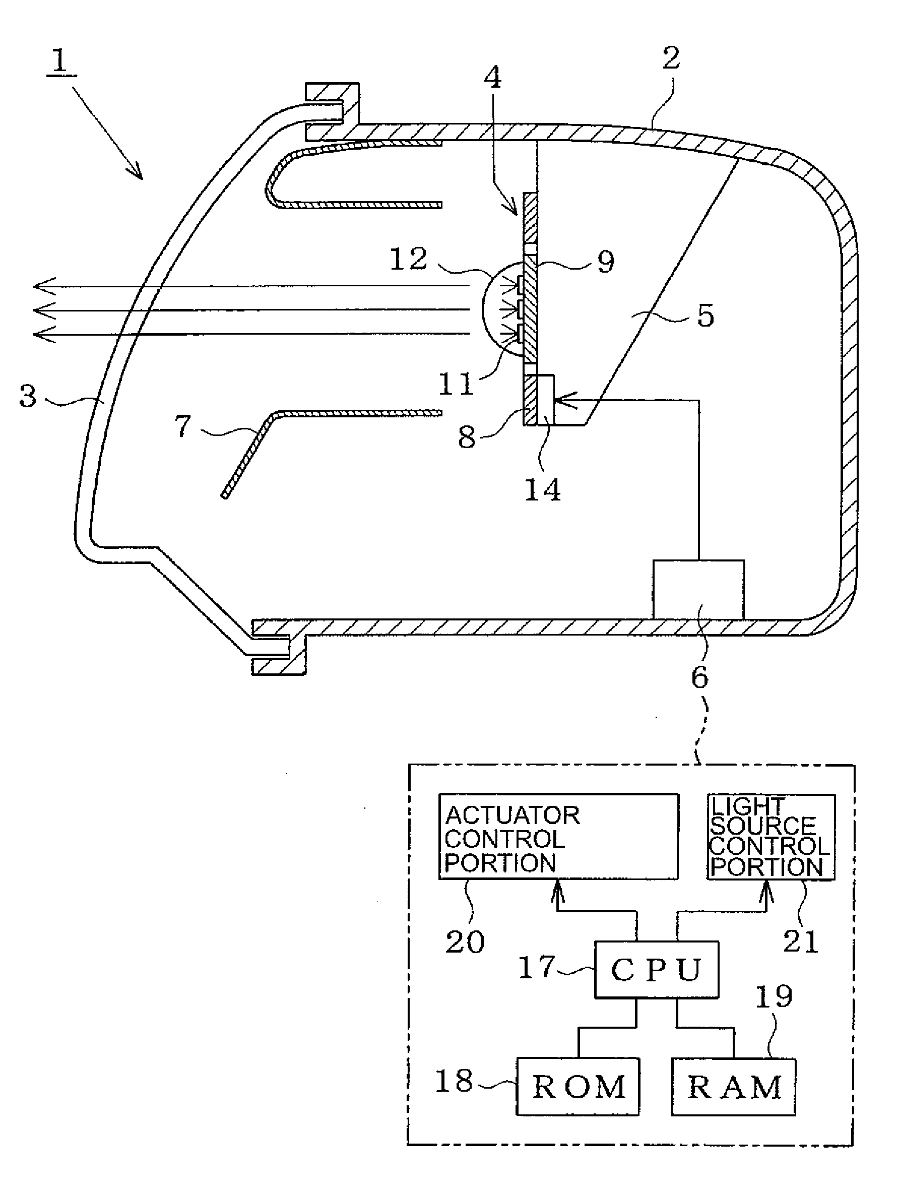
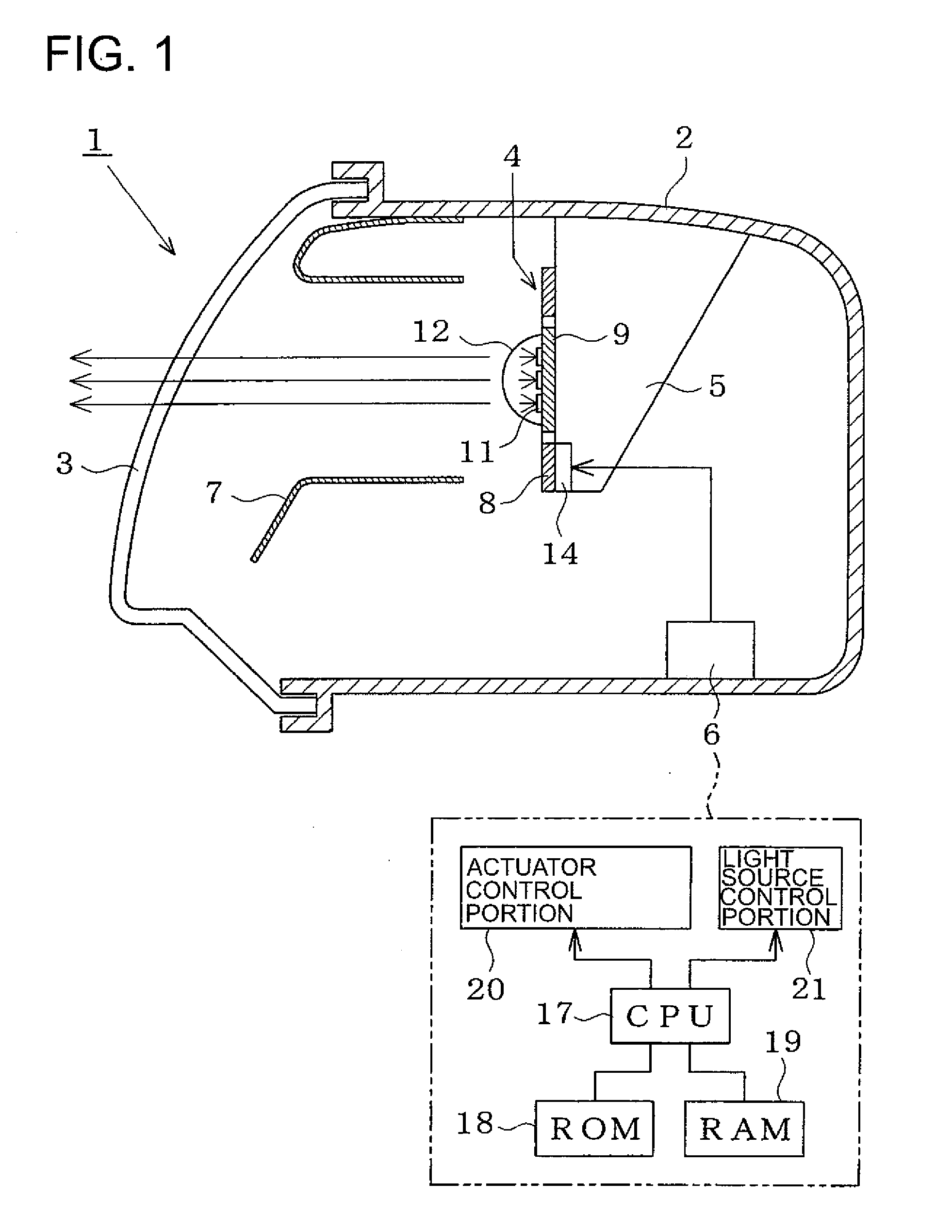
[0039]As shown in FIG. 1, the vehicular headlamp 1 of the first embodiment includes a housing 2 disposed on both left and right sides of a vehicle body front portion. A front surface of the housing 2 is covered by a translucent cover 3. A scanning actuator 4 is attached by a bracket 5 to a generally center portion of the housing 2. A control unit 6 is disposed in a bottom portion of the housing 2. An extension 7 is disposed between the scanning actuator 4 and the translucent cover 3.

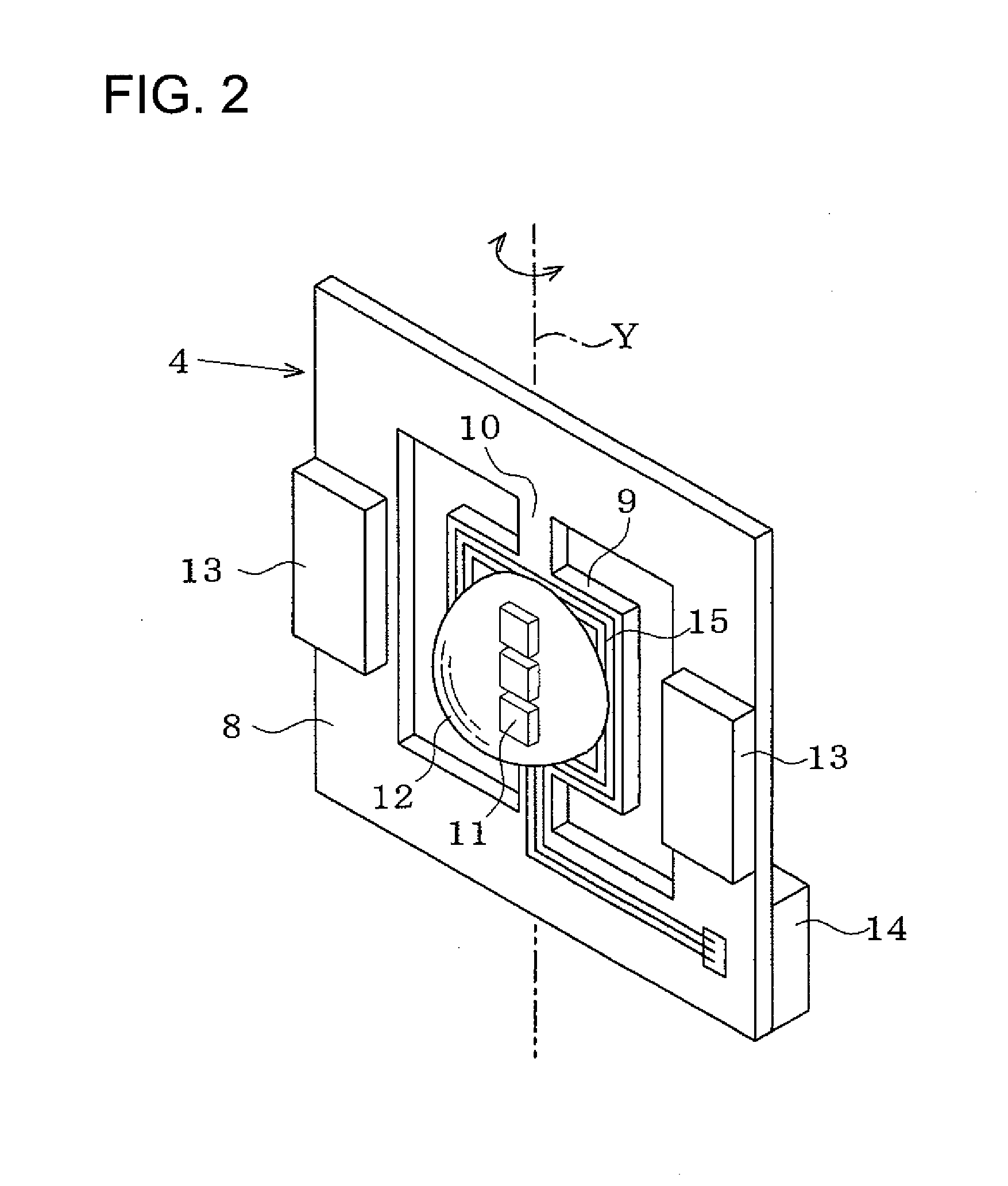
[0040]As shown in FIG. 2, the scanning actuator 4 has a rotating element 9, which is shaped as a flat plate, inside a quadrangular ring-like base 8. The base 8 is fixedly held by the bracket 5. The rotating element 9 is connected to the base 8 so as to reciprocatingly rotate in the right-left direction by a torsion bar 10 in a vertical axis (Y) direction. A light source 11 radiating visible light and a lens 12 allowing the visible light radiated from the light source 11 to pass therethrough to forward of...

third embodiment

[0061]As shown in FIG. 17, in a vehicular headlamp 51 of a third embodiment, a plurality of light sources 52, 53, 54 are combined with one mirror 33. Light from the light sources 52 to 54 is irradiated ahead of the vehicle via the mirror 33 and the projection lens 39. A two-axis actuator is used as the scanning actuator 38. The movement (angle and speed) of the outside and inside rotating elements 25, 26 is feedback-controlled by the actuator control portion 20. The light source control portion 21 includes drive circuits 55, 56, 57. The light output (light turning-off and light control) of the light sources 52 to 54 are separately controlled and synchronized with the movement of the rotating elements 25, 26.

[0062]When the scanning actuator 38 is stopped, the light sources 52, 53, 54 forms the basic patterns with different illuminance at different regions ahead of the vehicle. For example, as shown in FIGS. 18(a) and 18(b), the first light source 52 forms a basic pattern Bp1 with hig...


PUM


Abstract

A vehicular headlamp includes at least one a light source irradiating visible light and a lens allowing the visible light from the light source to pass through to forward of a vehicle. The light source and the lens are mounted in a rotating element. Alternatively, the vehicular headlamp includes at least one a light source irradiating visible light, and a mirror mounted on a rotating element and arranged to reflect the visible light from the at least one light source to forward of a vehicle. The vehicular headlamp also includes a scanning actuator for reciprocatingly rotating the rotating element so as to form a light distribution pattern forward of the vehicle and a light distribution control portion for controlling the scanning actuator such that a portion of the light distribution pattern is relatively bright.

Description

BACKGROUND OF INVENTION[0001]1. Field of the Invention[0002]The present invention relates to a vehicular headlamp that forms a variable light distribution pattern forward of a vehicle.[0003]2. Related Art[0004]Art for changing a light distribution pattern forward of a vehicle by driving an optical part in a lamp chamber is known. For example, Patent Document 1 discloses a vehicular headlamp that irradiates light from a light source to a paraboloidal reflective surface via a shielding plate and deflects a portion of luminous flux by driving a movable mirror on an optical path ahead of the paraboloidal reflective surface so as to change the light distribution pattern.[0005]Patent Document 2 discloses a vehicular headlamp in which a reflective surface that reflects light from a light source is structured from a number of micro mirror elements. In addition, an on / off state of the mirror elements, an intensity gradation and a tilt angle are digitally controlled separately so as to form a...

Claims


Application Information

Patent Timeline
Patent Type & Authority Applications(United States)
IPC IPC(8): B60Q1/00G05F1/00H01L33/58H01L33/60
CPCB60Q1/076B60Q1/1423B60Q2300/056B60Q2300/42B60Q2300/45F21Y2101/02F21S48/1154F21S48/1159F21S48/1742F21S48/1757F21W2101/10F21S48/1104F21Y2115/10F21S41/19F21S41/143F21S41/147F21S41/657F21S41/675F21S41/16F21W2102/155F21S41/151F21S41/176F21W2102/00
Inventor SATO, NORIKOKOMATSU, MOTOHIROUCHIDA, NAOKISUGIYAMA, TAKUOMOCHIZUKI, MITSUYUKI
Owner KOITO MFG CO LTD
Why Eureka
Try Eureka