Vehicular headlamp
a headlamp and headlamp technology, applied in semiconductor devices, light sources, lighting and heating apparatus, etc., can solve the problems of limited deflection effect of movable mirrors, narrow variable range, complicated structure, etc., and achieve the effect of complex structure and large rang
- Summary
- Abstract
- Description
- Claims
- Application Information
AI Technical Summary
Benefits of technology
Problems solved by technology
Method used
Image
Examples
first embodiment
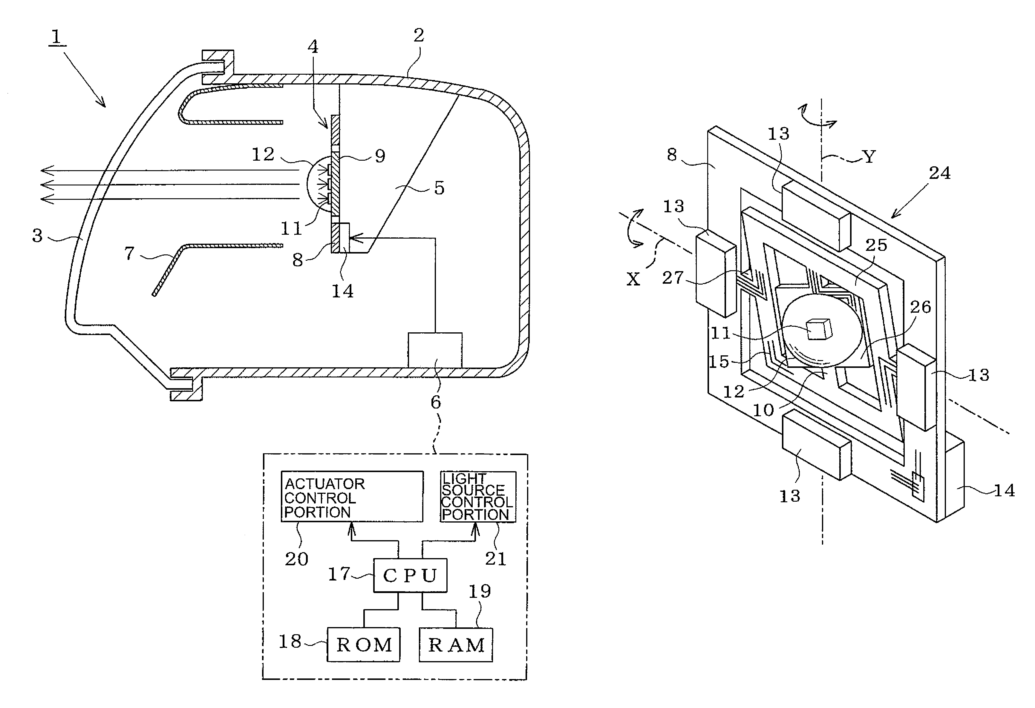
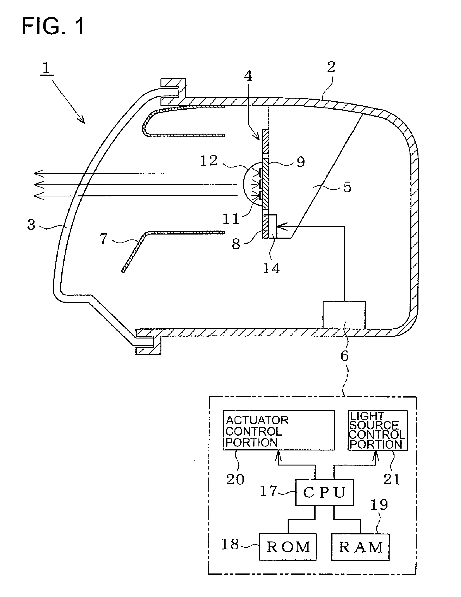
[0039]As shown in FIG. 1, the vehicular headlamp 1 of the first embodiment includes a housing 2 disposed on both left and right sides of a vehicle body front portion. A front surface of the housing 2 is covered by a translucent cover 3. A scanning actuator 4 is attached by a bracket 5 to a generally center portion of the housing 2. A control unit 6 is disposed in a bottom portion of the housing 2. An extension 7 is disposed between the scanning actuator 4 and the translucent cover 3.
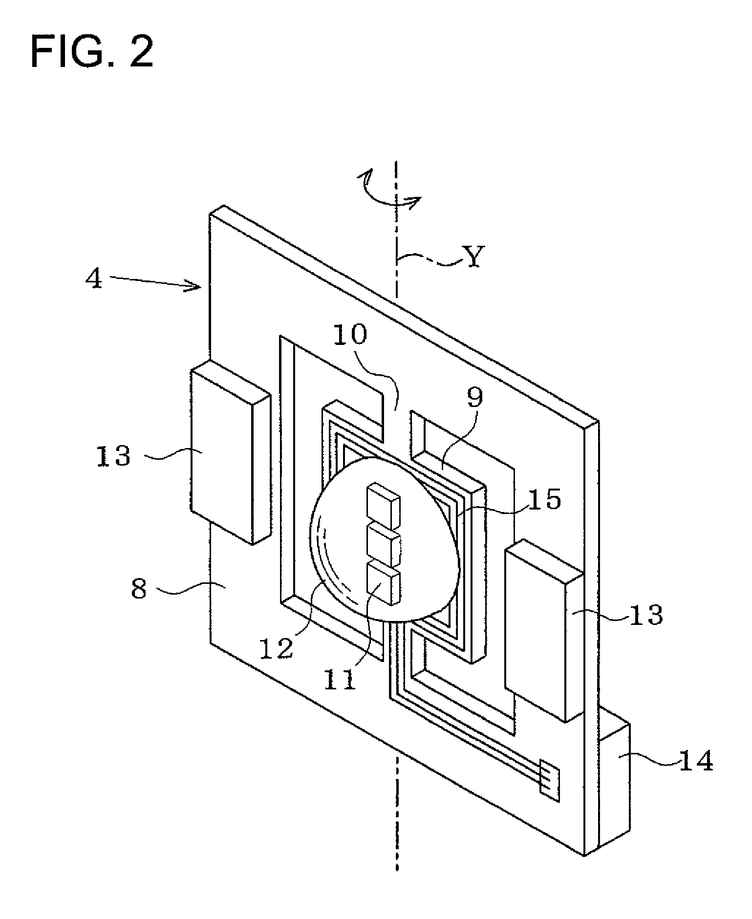
[0040]As shown in FIG. 2, the scanning actuator 4 has a rotating element 9, which is shaped as a flat plate, inside a quadrangular ring-like base 8. The base 8 is fixedly held by the bracket 5. The rotating element 9 is connected to the base 8 so as to reciprocatingly rotate in the right-left direction by a torsion bar 10 in a vertical axis (Y) direction. A light source 11 radiating visible light and a lens 12 allowing the visible light radiated from the light source 11 to pass therethrough to forward of...
second embodiment
[0052]As shown in FIG. 8, in a vehicular headlamp 31 of a second embodiment, a mirror 33 is mounted on a rotating element 9 of a scanning actuator 32 and reflects visible light from a light source 34 to the front of the vehicle. The scanning actuator 32 drives the rotating element 9 around the vertical axis at high speed and scans reflective light from the mirror 33 ahead of the vehicle so as to form a required light distribution pattern. The light source 34 is disposed near the control unit 6 separately from the scanning actuator 32. In the same manner as the first embodiment the control unit 6 is structured so as to control the angle and the speed of the rotating element 9 and the light output of the light source 34 so as to relatively illuminate a portion of the light distribution pattern.
[0053]As shown in FIG. 9(a), the light source 34 includes a light emission portion 35 emitting laser light, a cylindrical lens 36 forming laser luminous flux into a required shape, and a shieldi...
third embodiment
[0060]As shown in FIG. 17, in a vehicular headlamp 51 of a third embodiment, a plurality of light sources 52, 53, 54 are combined with one mirror 33. Light from the light sources 52 to 54 is irradiated ahead of the vehicle via the mirror 33 and the projection lens 39. A two-axis actuator is used as the scanning actuator 38. The movement (angle and speed) of the outside and inside rotating elements 25, 26 is feedback-controlled by the actuator control portion 20. The light source control portion 21 includes drive circuits 55, 56, 57. The light output (light turning-off and light control) of the light sources 52 to 54 are separately controlled and synchronized with the movement of the rotating elements 25, 26.
[0061]When the scanning actuator 38 is stopped, the light sources 52, 53, 54 forms the basic patterns with different illuminance at different regions ahead of the vehicle. For example, as shown in FIGS. 18(a) and 18(b), the first light source 52 forms a basic pattern Bp1 with hig...
PUM
 Abstract
Description
Claims
Application Information
 - R&D
- Intellectual Property
- Life Sciences
- Materials
- Tech Scout
- Unparalleled Data Quality
- Higher Quality Content
- 60% Fewer Hallucinations
Browse by: Latest US Patents, China's latest patents, Technical Efficacy Thesaurus, Application Domain, Technology Topic, Popular Technical Reports.
© 2025 PatSnap. All rights reserved.Legal|Privacy policy|Modern Slavery Act Transparency Statement|Sitemap|About US| Contact US: help@patsnap.com


