

Ball joint
a ball joint and ball bearing technology, applied in the direction of shafts, bearings, couplings, etc., can solve the problems of affecting the smooth movement of the ball shank with respect to the holder, premature wear, and the sliding surface of the two components is flawed, so as to prevent the displacement of the side lip portion on the tapered surface and reliably maintain the sealed state
- Summary
- Abstract
- Description
- Claims
- Application Information
AI Technical Summary
Benefits of technology
Problems solved by technology
Method used
Image

Examples
Embodiment Construction
[0015]In the following, the ball joint of the present invention will be described in detail with reference to the accompanying drawings.
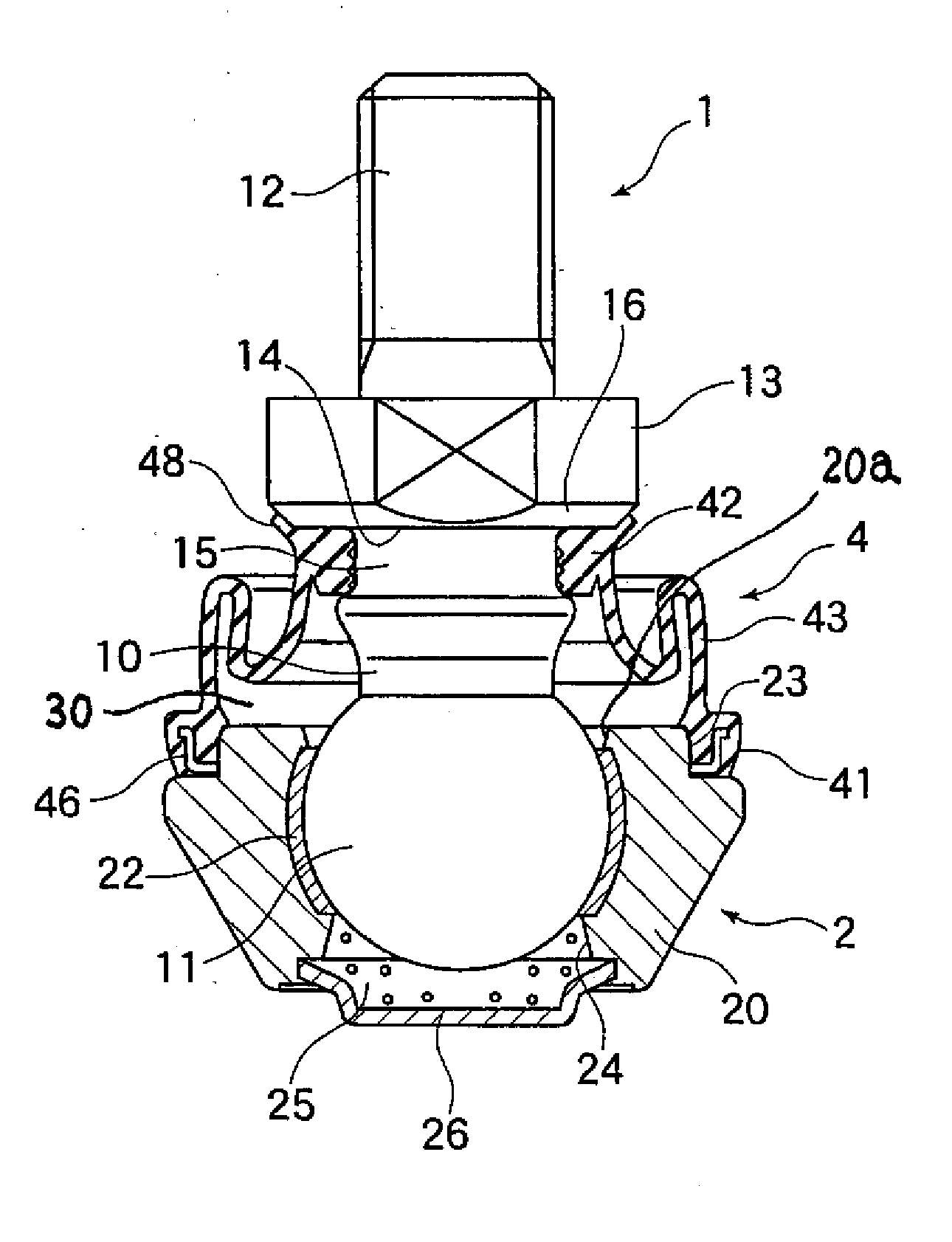
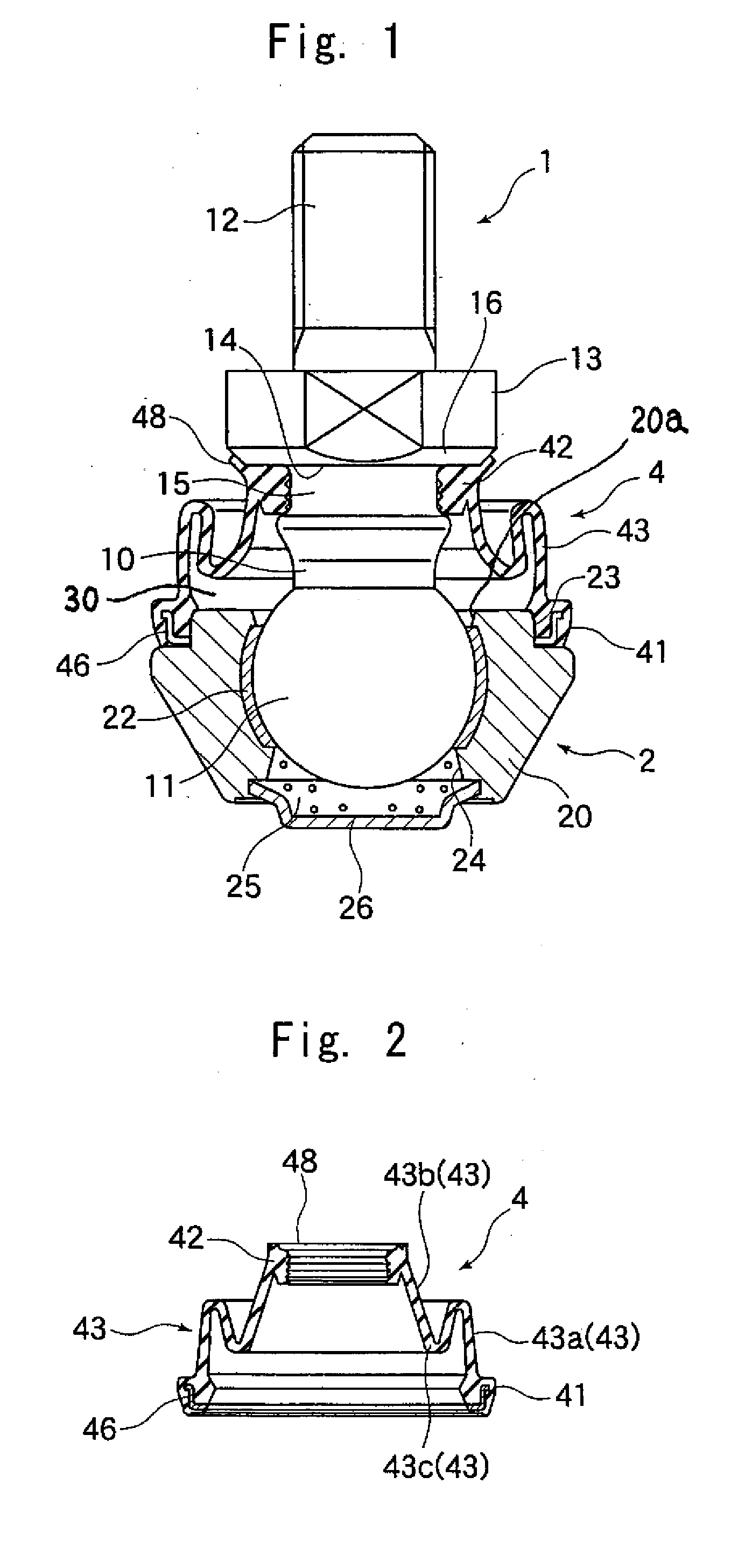
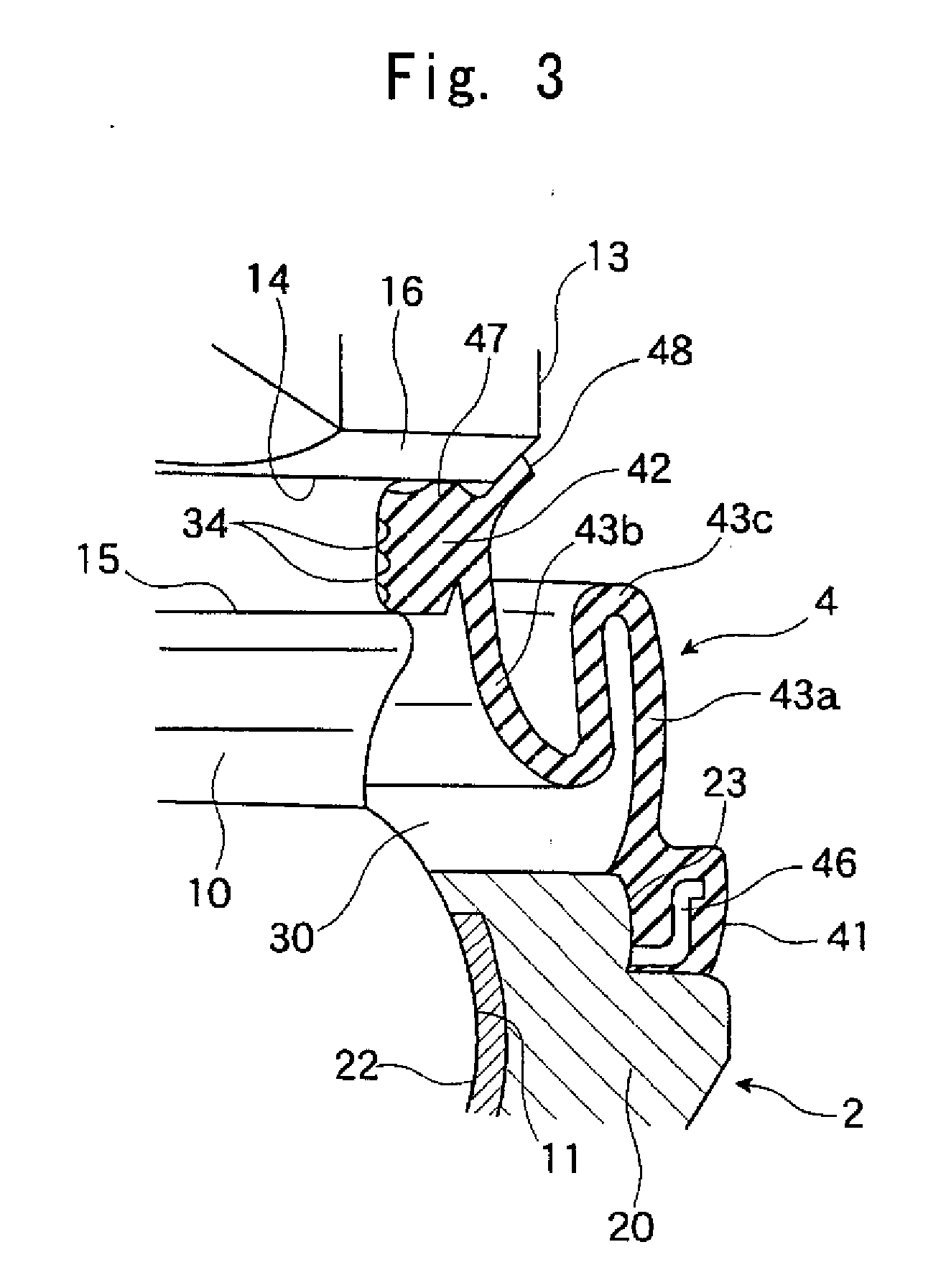
[0016]FIG. 1 shows a ball joint according to an embodiment of the present invention. In the drawing, numeral 1 indicates a ball shank, numeral 2 indicates a holder connected to the ball shank 1 swingably and rotatably, and numeral 4 indicates a boot seal mounted so as to cover the connecting portion between the ball shank 1 and the holder 2.
[0017]The ball shank 1 has a substantially columnar shaft portion 10 at the forward end of which a ball portion 11 is formed. To realize a smooth sliding contact with the holder 2, the ball portion 11 is formed by welding to the shaft portion 10 a bearing steel ball of high sphericalness. At the end of the shaft portion 10 on the side opposite to the ball portion 11, there is formed a male screw portion 12; a flange portion 13 is provided so as to be adjacent to the male screw portion 12; using the flange portion...
PUM
 Abstract
Description
Claims
Application Information