Control System for Electromagnetic Pumps

a control system and electromagnetic pump technology, applied in the direction of dynamo-electric machines, non-polarised relays, instruments, etc., can solve the problems of both membrane pumps driven by rotating motors and membrane pumps driven by electromagnets without, and neither type of membrane pumps combine the advantages of both rotating motors and electromagnets without, and lack the precision and accuracy needed to solve problems

Active Publication Date: 2009-02-19
XAVITECH AB
View PDF25 Cites 17 Cited by
  • Summary
  • Abstract
  • Description
  • Claims
  • Application Information

AI Technical Summary

Problems solved by technology

In the Swedish patent application SE7503408 optical sensors are used for securing that the pump does not reach its closing position by digitally reading a logical one or logical zero in order to stop or start the electromagnet, however this solution differs greatly from the solution described herein, because their solution lacks information on what happens during all the remaining time that is comprised of the time the movable part is in all the other positions than just the two closing positions that are read.
Even if existing electromagnetic driven membrane pumps many times achieve there purposes, none of these combine the advantages from both membrane pumps driven by a rotating motor and membrane pumps driven by electromagnets without any of the disadvantages entailed by both types.
This system differs greatly from the system described herein, because their system lacks the precision and accuracy needed to solve all the problems described herein and essentially aims to optimizing efficiency.
All the earlier mentioned problems result in that there exists a great potential for improving control systems for electromagnetic pumps.

Method used


Image

  • Control System for Electromagnetic Pumps
  • Control System for Electromagnetic Pumps

Examples


Embodiment Construction

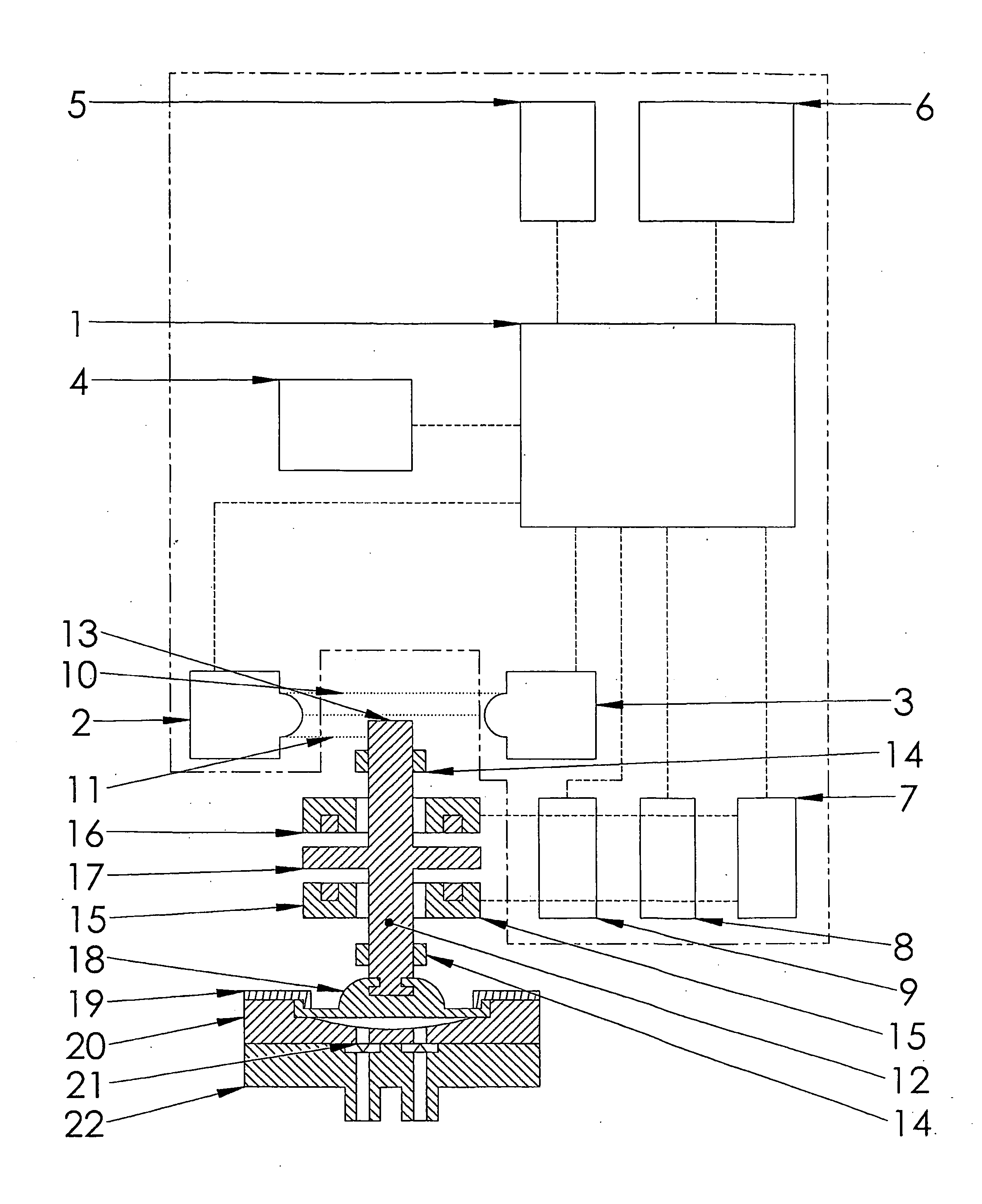
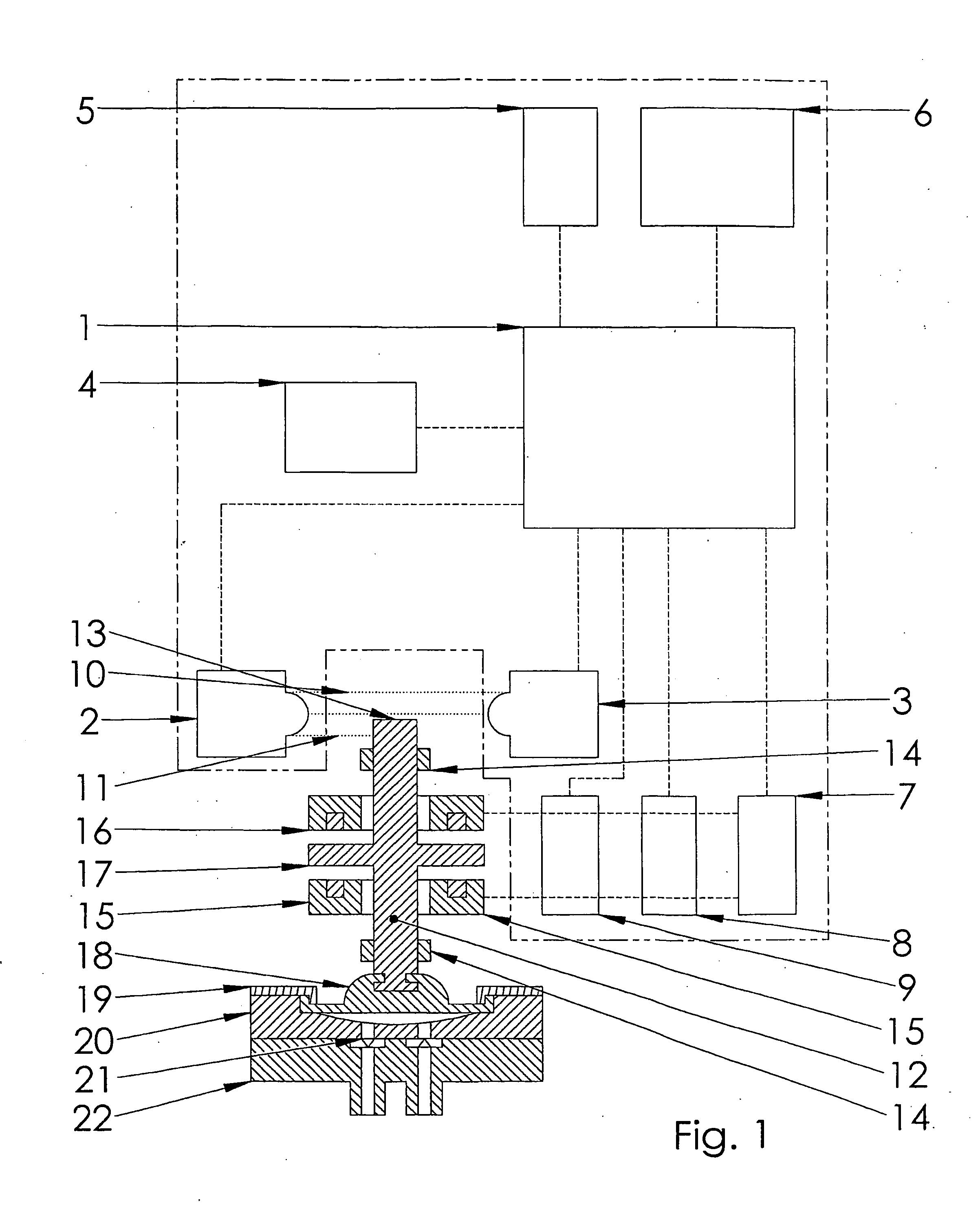
[0009]The invention will be described in detail in the following text with reference to the enclosed schematic drawing which shows, in an exemplifying purpose, the current preferred embodiment of the invention.

[0010]FIG. 1 shows a control system according to the first executed form of the present invention.

THE CONTROL SYSTEM

[0011]With reference to FIG. 1 a control system is shown according to the present invention. The system is driven by an electric power source that provides control voltage and supplies the system, via a voltage reader 5, with the energy needed to drive the system. The system consists of at least one microprocessor 1 that gathers all the data, stores the data, computes the data and sends the data onward. Data is gathered from at least one position sensor. Preferably the control system also contains at least one temperature sensor 4, at least one electric current meter 9 (ammeter) and at least one voltage measurer 8 (voltmeter). In alternative embodiments additiona...


PUM


Abstract

A control system for controlling electromagnetic pumps, such as electromagnetic driven membrane pumps, has at least one microprocessor and at least one sensor, the microprocessor controlling the power supply to at least one electromagnet whose changes in emitted magnetic field causes at least one moving part, directly or indirectly, to perform an oscillating pumping movement. The control system has at least one positioning sensor which senses the moving part's position in the electromagnetic driven pump. By use of the positioning sensor's measurements, the pump can be controlled with great accuracy. A method for controlling electromagnetic pumps is also provided.

Description

TECHNICAL FIELD[0001]The present invention concerns a control system for operating electromagnetic pumps. More specifically, the invention relates to a control system and method in accordance with the claims.TECHNICAL BACKGROUND[0002]Electromagnetic pumps that apply pressure or negative pressure are found in a large variety of variations and sizes and are used in many different applications, everything from large industrial pumps to very small pumps for medical purposes. The diverse areas of use for electromagnetic pumps such as membrane pumps results in a plethora of requirements put upon the performance of such pumps. A significant problem for buyers of membrane pumps is that the supply of pumps from manufacturers is to a large degree standardized to just a few different models, largely because pump manufacturers seek economies of scale in their production. The limited diversity of pumps means that there exists a need for more efficient control systems. This would allow manufactur...

Claims


Application Information

Patent Timeline
Patent Type & Authority Applications(United States)
IPC IPC(8): F04B49/06
CPCF04B43/0081F04B43/04G05B15/02F04B2201/0201F04B49/065F04B13/00F04B2203/0402H01H51/12H02K33/10H02K33/12H02K11/22
Inventor STENBERG, JOHAN
Owner XAVITECH AB
Why Eureka
Try Eureka