Ink Discharging Apparatus and Ink Discharging Method

a technology of ink cartridge and ink cartridge, which is applied in the direction of coating, printing, instruments, etc., can solve the problems of structurally very difficult to provide such a cap member, so as to achieve the effect of deterioration of image quality

Inactive Publication Date: 2009-02-19
SHARP KK
View PDF5 Cites 0 Cited by
  • Summary
  • Abstract
  • Description
  • Claims
  • Application Information

AI Technical Summary

Benefits of technology

[0009]However, the above-described conventional art has a disadvantage in that the thickness of a film formed by ink discharge increases as ink density inc

Problems solved by technology

However, the above-described conventional art has a disadvantage in that the thickness of a film formed by ink discharge increases as ink density increases on account of evaporation of an ink solvent, with the result that the quality of an image is deteriorated.
As a result, even if the same number of droplets are discharged onto defective pixels, the differences in the ink density result in differences in thickness among the films formed by the ink discharge, and such differences in thickness in the films of the repaired pixels induce the deterioration of the image quality.
However, it is structurally very difficult to provide such

Method used


Image

  • Ink Discharging Apparatus and Ink Discharging Method
  • Ink Discharging Apparatus and Ink Discharging Method
  • Ink Discharging Apparatus and Ink Discharging Method

Examples


Embodiment Construction

[0039]The following will discuss an embodiment of the present invention with reference to FIGS. 1 through 6.

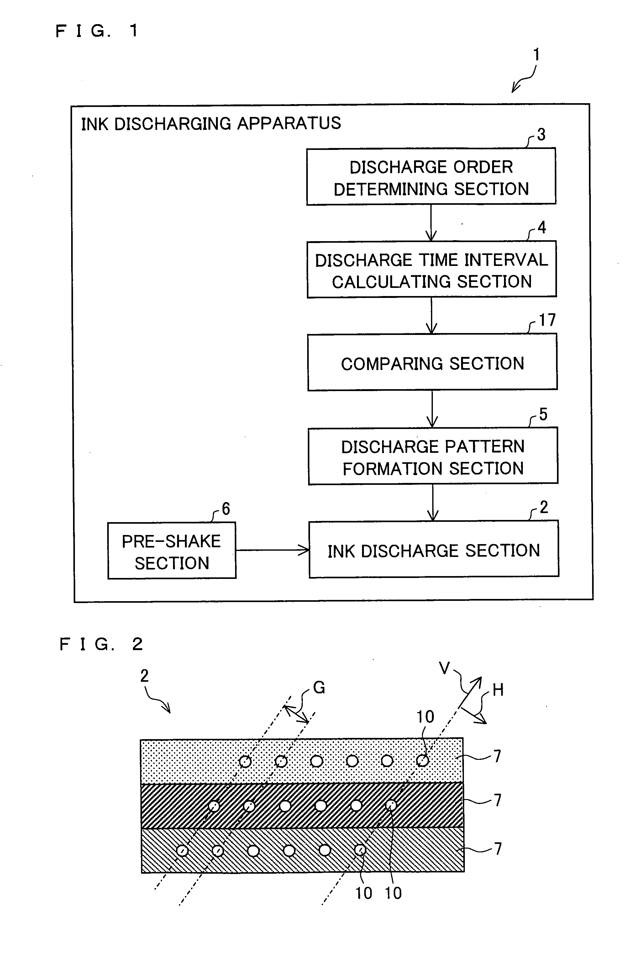
[0040]FIG. 1 relates to an embodiment of the present invention and is a block diagram showing a substantial part of an ink discharging apparatus 1. The ink discharging apparatus 1 includes an ink discharge section 2. The ink discharge section 2 is arranged to be movable relative to a CF panel formed on a substrate in order to discharge ink onto defective pixels scattering on the CF panel.

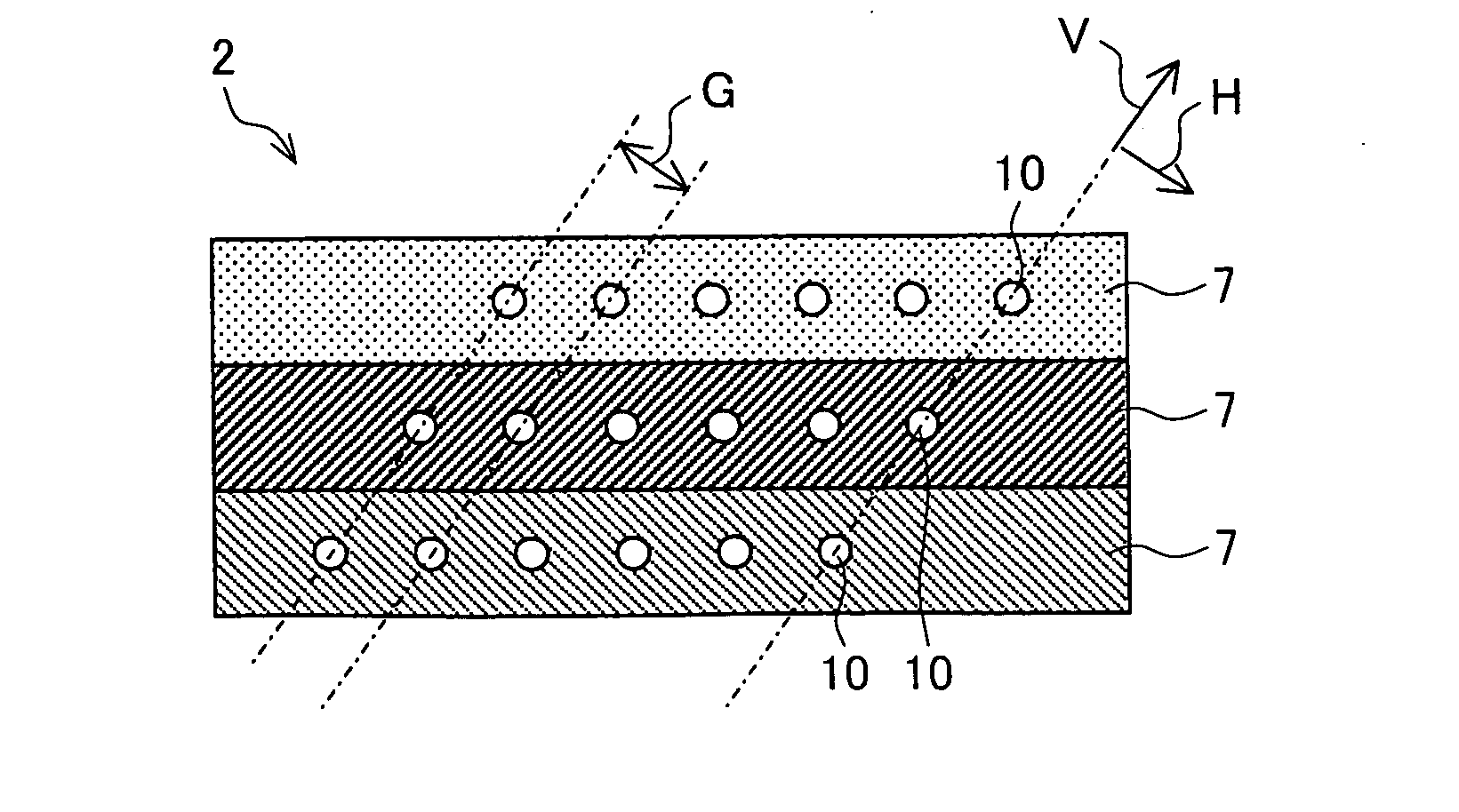
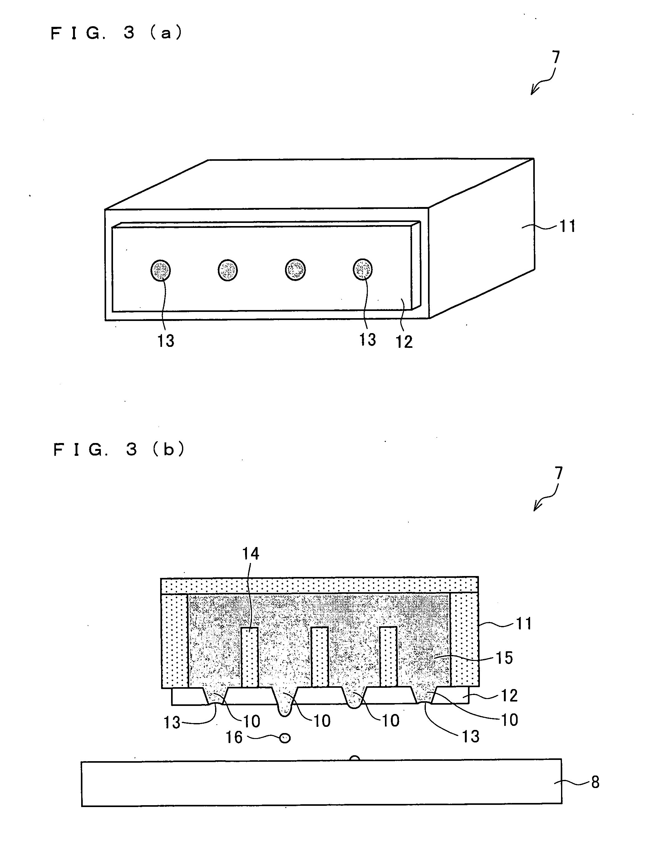
[0041]FIG. 2 is a schematic of the ink discharge section 2. The ink discharge section 2 has three heads 7 for red (R), green (R), and blue (B) colors, respectively. Each head 7 is provided with nozzles 10.

[0042]In the head 7 shown in FIG. 2, the nozzles 10 are arranged to form a parallelogram in such a way that the outermost nozzles 10 are aligned along the main scanning direction V of the ink discharge section 2, when the ink discharge section 2 is rotated in the anticlockwise direction. As t...


PUM


Abstract

The present invention provides an ink discharging apparatus capable of forming a high-quality film. An ink discharging apparatus (1) includes: an ink discharge section (2) which is movable relative to a substrate in order to discharge ink onto plural defective pixels scattering on the substrate; and a discharge time interval calculating section (4) which calculates a discharge time interval from the previous ink discharge to the ink discharge of this time, in accordance with the order of ink discharge onto plural defective pixels. The ink discharge section (2) controls an amount of discharged droplets of ink or the number of discharged droplets, in accordance with the discharge time interval calculated by the discharge time interval calculating section (4).

Description

TECHNICAL FIELD[0001]The present invention relates to an ink discharging apparatus and an ink discharging method, which make it possible to quickly and precisely discharge ink onto an ink discharge target such as a defective pixel.BACKGROUND ART[0002]Ink discharging technologies have recently been not only used for consumer-use printers but also widely used for apparatuses for manufacturing color filter panels (hereinafter, CF panels) of liquid crystal displays and for other manufacturing apparatuses. As such, the use of the technologies has been diversified.[0003]An example of the above is an ink jet patterning technology by which a pattern is formed on a substrate by utilizing the ink discharging technologies. The ink jet patterning technology is a technology to directly print a miniature pattern on a substrate by discharging a small amount of liquid (ink) by an ink discharging apparatus. This ink jet patterning technology has drawn attention as a technology usable in process with...

Claims


Application Information

Patent Timeline
IPC IPC(8): B05D5/12B05C11/00
CPCB41J2/1707G02F1/133516B41J2202/09
Inventor YOSHIOKA, CHIYOSHIKAWAI, HIDETSUGU
Owner SHARP KK
Why Eureka
Try Eureka