

Nano-enhanced smart panel
a smart panel and nano-enhanced technology, applied in the field of modular construction of composite panels, can solve the problems of increased space and higher cost of applications, and achieve the effect of convenient construction
- Summary
- Abstract
- Description
- Claims
- Application Information
AI Technical Summary
Benefits of technology
Problems solved by technology
Method used
Image

Examples
example embodiments
[0038]The example embodiments described herein are provided for illustrative purposes, and are not limiting. Further structural and operational embodiments, including modifications / alterations, will become apparent to persons skilled in the relevant art(s) from the teachings herein.
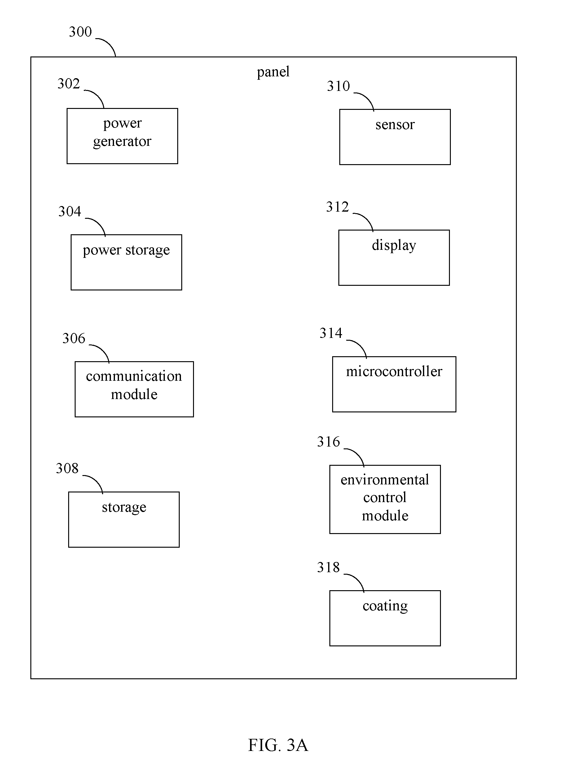
[0039]Methods, systems, and apparatuses are provided herein for a “smart” panel that may be self-contained, includes one or more functions, and may be modular in construction. In embodiments, the smart panel is assembled to be lightweight, while being stiff or flexible (as desired for a particular application), strong, and tough. The smart panel may include one or more functional elements to enable one or more functions, such as a computing / decision-making function, power generation, power storage, wireless communications capability, memory, one or more sensor functions, display capability for graphics / video, programmatically changing a color of the panel, and / or further functions. Furthermore, a smart pa...
example smart panel embodiments
[0047]Example embodiments for smart panels are described in this section. Such example embodiments are provided for purposes of illustrations, and are not intended to be limiting. In embodiments, smart panels may include any number of layers, any combination of types of layers, and any number and type of functional elements that are included in any number of layers. Further structural and operational embodiments, including modifications / alterations, will become apparent to persons skilled in the relevant art(s) from the teachings herein.
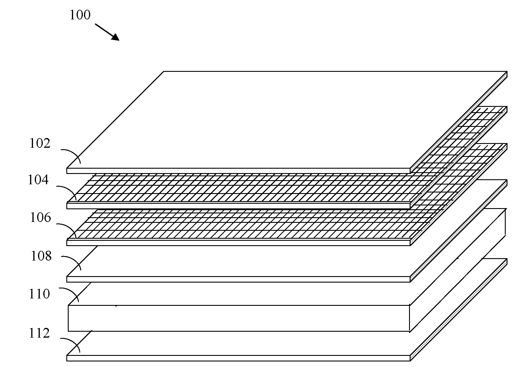
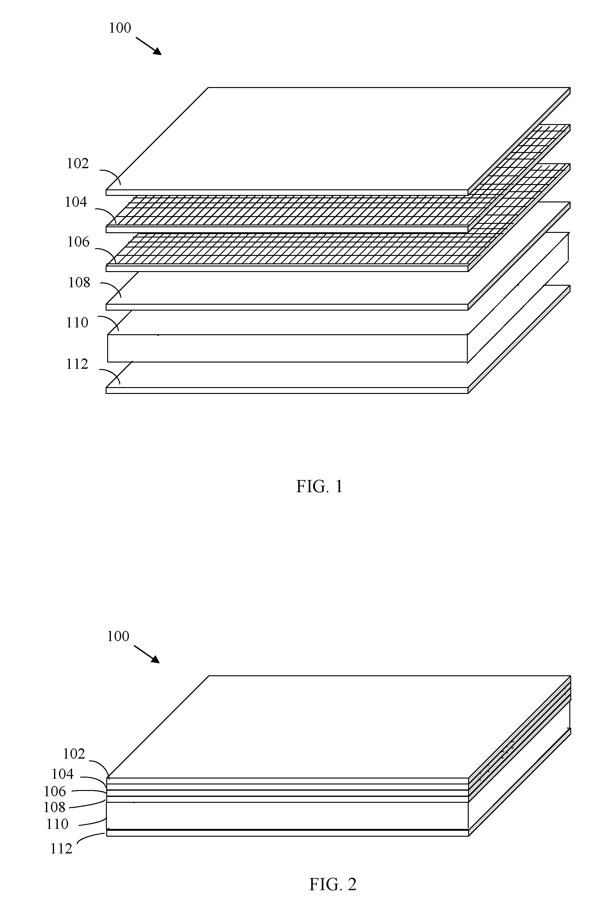
[0048]For example, FIG. 1 shows a perspective exploded view of a panel 100, according to an embodiment of the present invention. FIG. 2 shows a perspective side view of panel 100, in non-exploded form. As shown in FIGS. 1 and 2, panel 100 includes a first layer 102, a second layer 104, a third layer 106, a fourth layer 108, a fifth layer 110, and a sixth layer 112. In FIG. 2, first layer 102 is attached to second layer 104, second layer 104 is attach...
example assembly embodiments
FOR SMART PANELS
[0103]Smart panels may be assembled in a variety of ways, according to embodiments. For instance, FIG. 11 shows a flowchart 1100 for fabricating a smart panel, according to an example embodiment of the present invention. Flowchart 1100 may be performed by a variety of assembly systems, which may incorporate any suitable manual, mechanical, electrical, chemical, and / or other fabrication techniques. For example, FIG. 12 shows a smart panel fabrication system 1200, according to an embodiment of the present invention. For illustrative purposes, flowchart 1100 is described with respect to smart panel fabrication system 1200 shown in FIG. 12. As shown in FIG. 12, system 1200 includes a layer fabricator 1202, a layer attacher 1204, and a panel post-processor 1206. Further structural and operational embodiments will be apparent to persons skilled in the relevant art(s) based on the discussion regarding flowchart 1100. Flowchart 1100 is described as follows.
[0104]Flowchart 11...
PUM
| Property | Measurement | Unit |
|---|---|---|
| Shape | aaaaa | aaaaa |
| Adhesivity | aaaaa | aaaaa |
Abstract
Description
Claims
Application Information