Dental Retainer

a technology of retainers and teeth, applied in dental tools, dental surgery, medical science, etc., can solve the problems of affecting the root of teeth, affecting the effect of teeth roots, and affecting the use of labial bow materials

Inactive Publication Date: 2009-02-19
BIOMERS PTE
View PDF14 Cites 14 Cited by
  • Summary
  • Abstract
  • Description
  • Claims
  • Application Information

AI Technical Summary

Benefits of technology

[0104]Preferably, the kit further comprises a canine stabilization component configured to be in alignment with at least one canine when the dental retain...

Problems solved by technology

Materials commonly used for labial bows currently have several associated problems.
However, such stainless steel wire exhibits high stiffness, resulting in the application of relatively heavy forces on teeth, which may have a detrimental effect on the teeth roots.
Roots have been known to get shortened and weaker under the effect of heavy forces.
Additionally, stiff stainless steel wire is also known to cause abrasion to tooth enamel.
A further problem associated with the use of stainless steel is that the poor aesthetic quality of stainless steel may have a negative effect on patient compliance.
Lack of proper retention, due to patients not wearing these retainers as often as required may result in a corrected tooth moving out of position.
When this occurs it may take a much longer time to correct the tooth again.
However, the use of thermoplastic labial bows has other inherent disadvantages.
In addition, thermoplastic material is not as resilient as stainless steel.
The amount of adjustment that can be carried out is limited, as repeated adjustments of the thermoplastic may result in the labial bow ...

Method used


Image

  • Dental Retainer
  • Dental Retainer
  • Dental Retainer

Examples


Embodiment Construction

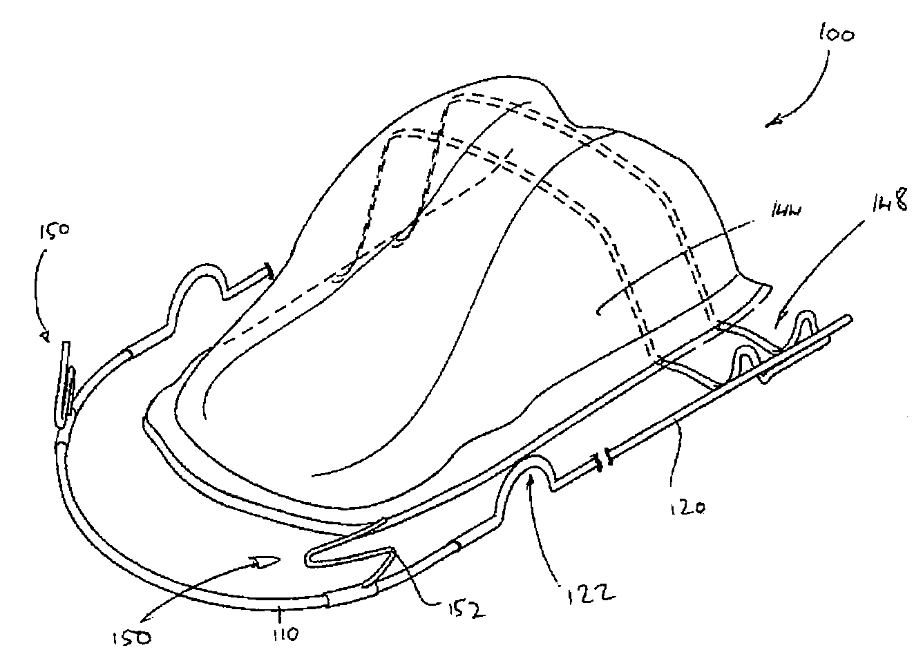
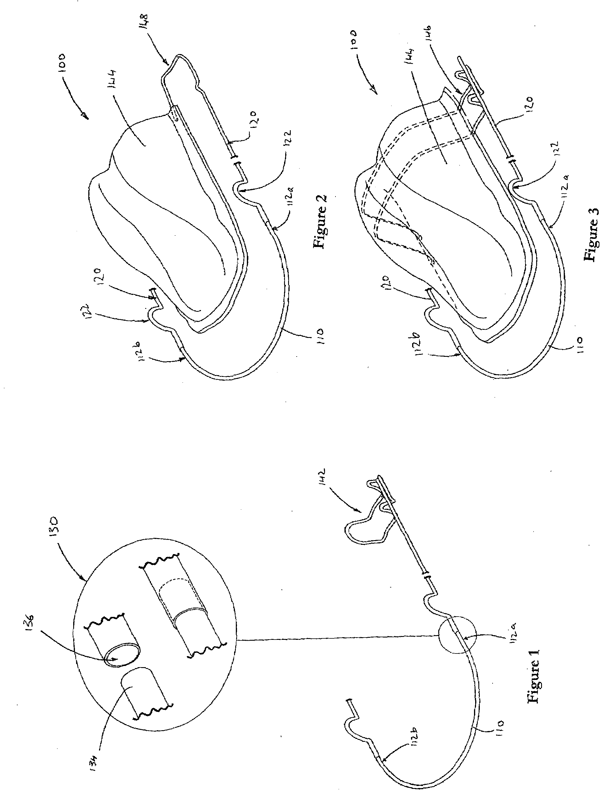
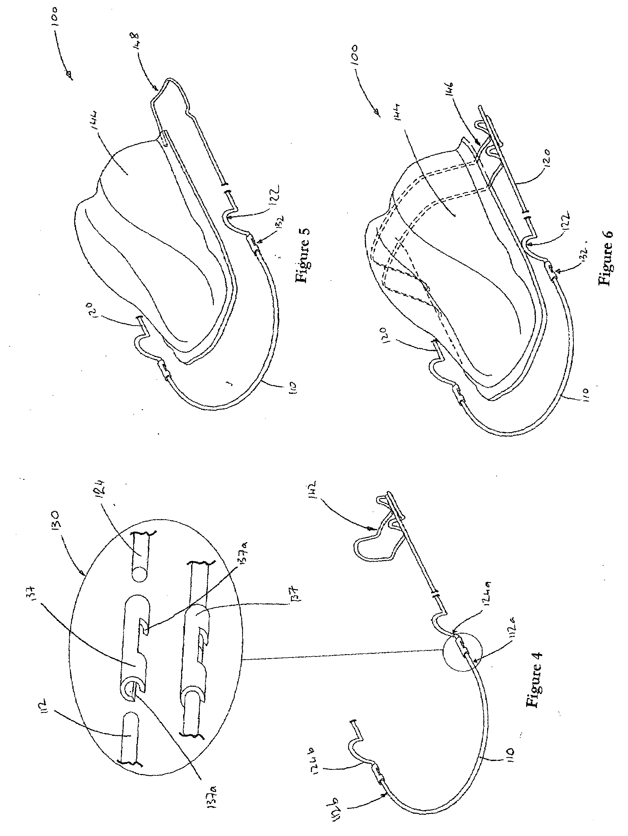
[0134]With reference to the above drawings, a dental retainer according to the invention is generally indicated by the numeral 100.

[0135]In one embodiment now described there is provided a dental retainer 100, suitable for use in retaining a user's teeth (not shown) in position, said dental retainer 100 comprising a curved labial bow member 110 suitable for abutment against the labial side of a row of teeth of a user, said bow member 110 comprising reinforcing fibers 115 and a polymer matrix 117, as shown in FIG. 20 and as disclosed in PCT publication number WO 2004 / 111112, which is incorporated herein by reference. The bow member 110 is envisaged as being circular in cross section, although it could also be of a flattened shape in cross section., and is configured and dimensioned to extend operationally from a first end 112a to a second end 112b along the labial side of a user's teeth from at least a pre-molar to a pre-molar on an opposed side of a user's mouth. The bow member 110 ...


PUM


Abstract

The invention provides a dental retainer 100, suitable for use in retaining a user's teeth (not shown) in position, said dental retainer 100 comprising a curved labial bow member 110 suitable for abutment against the labial side of a row of teeth of a user, said bow member 110 being composed of a fiber reinforced matrix of a suitable thermoplastic material. The bow member 110 is configured and dimensioned to extend operationally from a first end 112a to a second end 112b along the labial side of a user's teeth from at least a pre-molar to a pre-molar on an opposed side of a user's mouth. The dental retainer 100 further comprises a pair of support members 120 which are connected to the ends 112a &b of the labial bow member 110 at their anterior ends 124a &b respectively. Preferably, the support members 120 are removably connected to the labial bow member 110 by means of a connector 130. The bow member 110 and the support member 120 are mounted to a user's teeth operationally by means of a mounting device, such as an Adam's clasp 142, cross over members 146 connected to a base plate 144, or a loop member 148 suitable for extending around a user's back molar to a base plate 144. The dental retainer 100 further includes a canine stabilization component 150 for stabilising the dental retainer against a user's canine teeth.

Description

FIELD OF THE INVENTION[0001]The present invention relates to a dental retainer. More particularly but not exclusively it relates to a dental retainer utilising composite materials technology, and which is suitable for use within a user's mouth for encouraging towards and / or retaining pre-corrected teeth in their corrected position.BACKGROUND OF THE INVENTION[0002]Dental retainers are widely known in dentistry. Dental retainers are devices which are worn within a user's mouth and which are used to retain teeth in their corrected state after they have been corrected by prior treatment. A typical retainer design is the “Hawley” design. This typically comprises a rigid metal wire made in the shape of a bow to stay in contact with the anterior or labial side of a line of corrected teeth, especially the incisors. Such a bow is called a labial bow. The labial bow provides anterior retention of the teeth. It discourages unwanted tooth movement and exerts forces on the teeth only in response...

Claims


Application Information

Patent Timeline
IPC IPC(8): A61C7/08
CPCA61C7/08A61C7/22A61C7/20
Inventor FATHIANATHAN, MERVYNGOPAL, RENUGASARAN, A.P.A. BINDUCHOUDHURY, RACHEL SHANTIKAREN, TEO CHIEH YINALIPHTRIAS, GEORGE
Owner BIOMERS PTE
Why Eureka
Try Eureka