Increased inkjet printed density

a technology of inkjet printing and density, applied in printing, typewriters, duplicating/marking methods, etc., can solve the problem of more difficult to achieve good densities, and achieve the effect of improving the printed density

Inactive Publication Date: 2009-02-26
EASTMAN KODAK CO
View PDF4 Cites 31 Cited by
  • Summary
  • Abstract
  • Description
  • Claims
  • Application Information

AI Technical Summary

Benefits of technology

[0009]The present invention provides a novel method of improving the printed density when dye based inks are used to create an inkjet image, especially when used with porous inkjet media. The invention is compatible with roll to roll manufacturing.

Problems solved by technology

However, when dye based inks are used, it is more difficult to achieve good densities, even when a mordant is included in the receiver formulation.

Method used


Image

  • Increased inkjet printed density
  • Increased inkjet printed density
  • Increased inkjet printed density

Examples


example

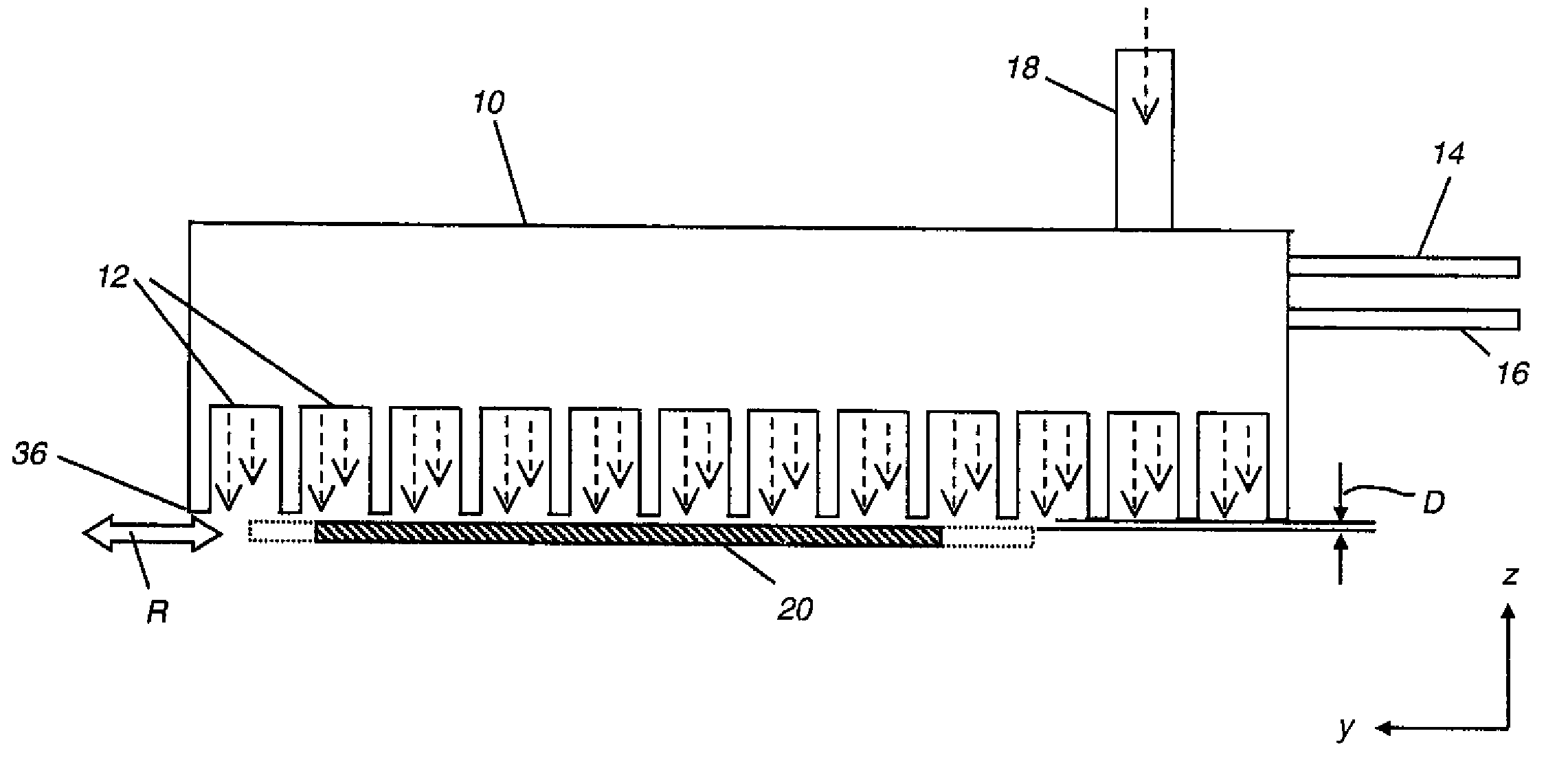
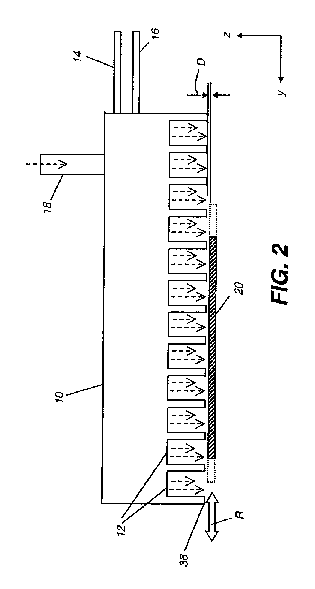
[0030]Three pieces of commercially available porous inkjet media (Kodak Everyday Picture Paper) were taken and on two of these samples layers of Al2O3 of various thicknesses were deposited directly onto the surface of the media using AP-ALD. Coating A had a 5 nm layer of Al2O3 deposited on the surface of the inkjet receiver and coating B had a 15 nm layer of Al2O3 deposited on the surface of the inkjet receiver using the conditions shown in Table 1. The other sample was left untreated to act as a comparison (the control).

TABLE 1AP-ALD conditions used to deposit layers of Al2O3Bubbler 1MaterialWaterFlow rate22 ml / minBubbler 2MaterialTrimethyl aluminiumFlow rate48 ml / minCarrier gas flowInert (N2)2000 ml / minWater (compressed air)300 ml / minMetal (N2)200 ml / minTemperaturePlaten95-105° C.Coating Head50° C.Deposition SettingsPlaten speed50 mm / secHead height55 μmCoating ANo. of oscillations 50Thickness of Al2O3 Layer~5 nmCoating BNo. of oscillations100Thickness of Al2O3 Layer~15 nm

[0031]An ...


PUM

PropertyMeasurementUnit
thickaaaaaaaaaa
thickaaaaaaaaaa
thickaaaaaaaaaa

Abstract

A method of improving the density of an inkjet image comprising the step of printing the image on an inkjet receiver having a layer of Al2O3 less than 100 nm thick deposited on the surface thereof.

Description

FIELD OF THE INVENTION[0001]This invention relates to the general technical area of inkjet printing, in particular to increasing the density of the final inkjet image.BACKGROUND OF THE INVENTION[0002]Inkjet inks typically comprise an ink vehicle and a colorant, which may be a dye or a pigment.[0003]Most commercial photo-quality inkjet receivers can be classified in one of two categories according to whether the principal component material forms a layer that is “porous” or “non-porous” in nature. Porous receivers comprise of inorganic materials with a polymeric binder, which absorb ink by capillary action. Because they absorb ink very quickly they have become the preferred technology as the speed of printing and quantity of ink being laid down is increasing. At the same time, some manufacturers of desktop printers are beginning to use pigmented inks while others are maintaining their dye based ink systems, resulting in a desire to be able to achieve acceptable images when either typ...

Claims


Application Information

Patent Timeline
Patent Type & Authority Applications(United States)
IPC IPC(8): B41J3/407
CPCB41M5/5218
Inventor BAKER, JULIE
Owner EASTMAN KODAK CO
Why Eureka
Try Eureka