
Advanced dynamic stitching method for multi-lens camera system

a dynamic stitching and multi-lens technology, applied in the field can solve problems such as the shift of stitching points, and achieve the effects of reducing the parallax phenomenon of multi-lens camera systems, increasing accuracy, and saving computation power of block matching

Inactive Publication Date: 2009-02-26
SONY TAIWAN
View PDF17 Cites 28 Cited by
  • Summary
  • Abstract
  • Description
  • Claims
  • Application Information

AI Technical Summary

Benefits of technology

[0003]Accordingly, the present invention provides a fast and effective search engine to update stitching points dynamically so that the parallax phenomenon can be compensated.
[0005]Therefore, according to the present invention, an advanced dynamic stitching method which suppresses the parallax phenomenon of multi-lens camera system is disclosed. Using feature detection and edge detection increases the accuracy and saves the computation power of block matching. The improved method in the invention dynamically adjusts the stitching point so that the parallax phenomenon can be ignored, and a seamless stitched image can be produced.

Problems solved by technology

However, most of this kind of multi-lens systems have parallax phenomenon, which means the stitching point will shift when an object moves from the near to the far.

Method used


Image

  • Advanced dynamic stitching method for multi-lens camera system
  • Advanced dynamic stitching method for multi-lens camera system
  • Advanced dynamic stitching method for multi-lens camera system

Examples


Embodiment Construction

[0011]In the following description, like parts are marked with the same reference numerals throughout the specification and drawings.

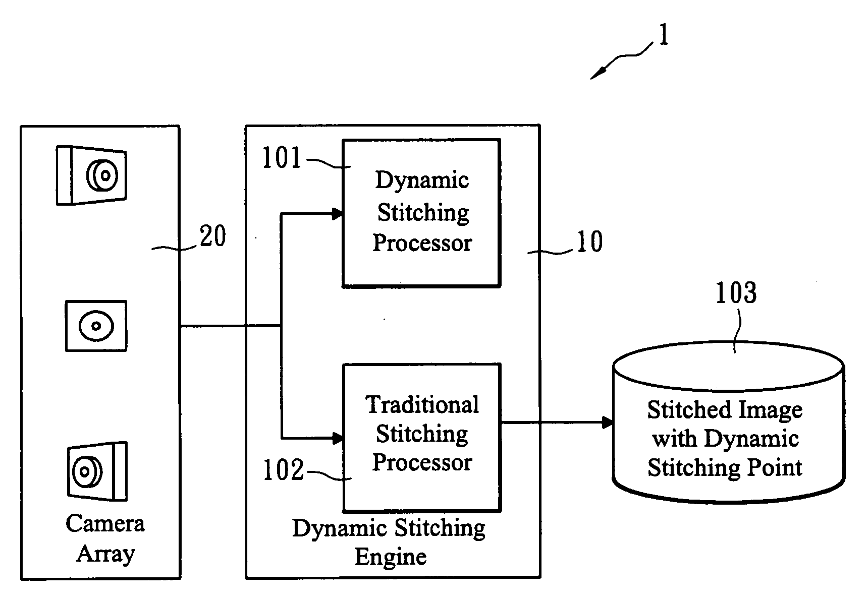
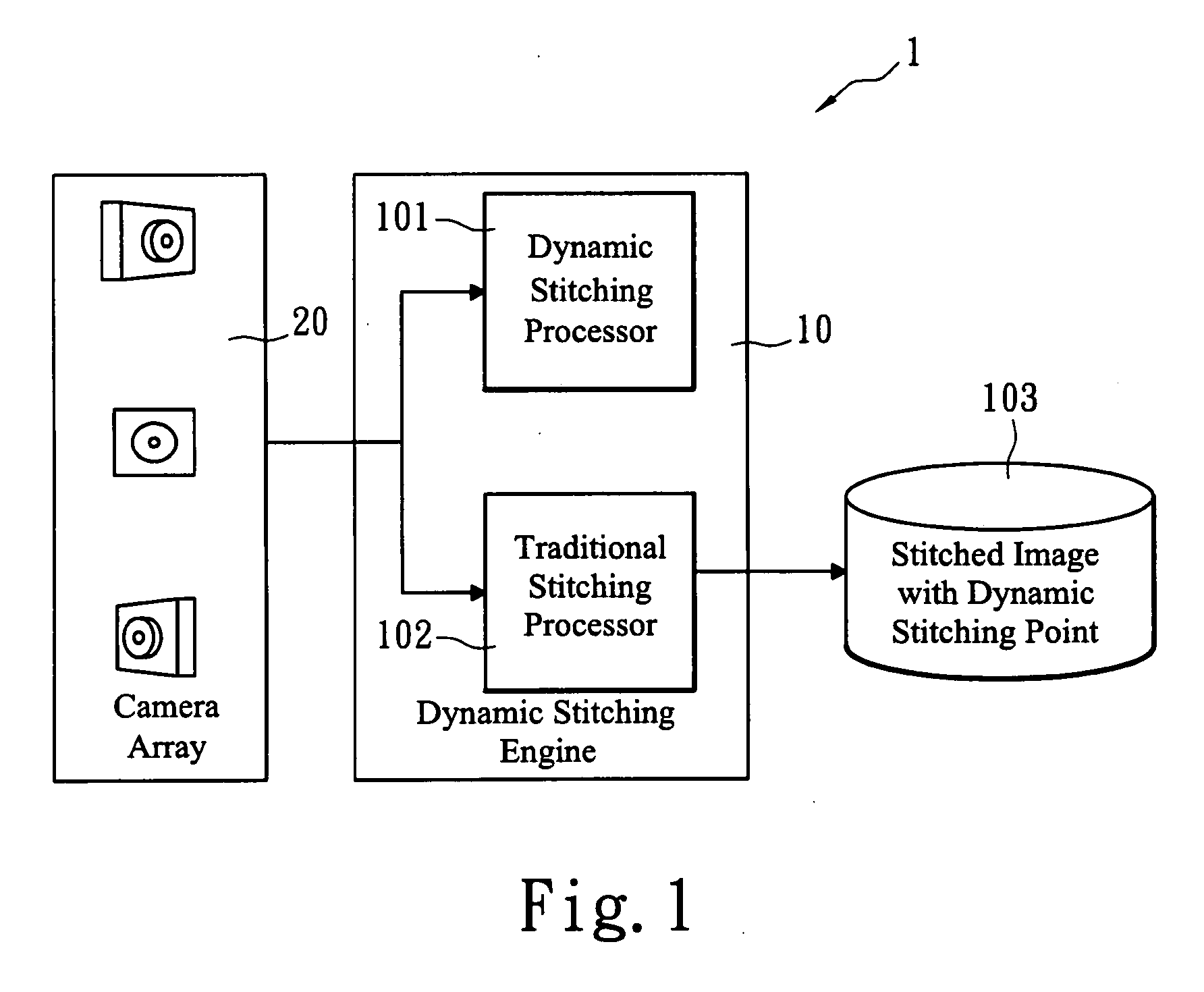
[0012]FIG. 1 describes the overview of a dynamic stitching system 1. A dynamic stitching engine 10 receives images or video streams from a multi-lens camera array 20. An input data is sent to a dynamic stitching processor 101 to update stitching points 122 if the distance of object changes. A traditional stitching processor 102 transforms input images and stitches them into one image according to the updated stitching points 122. Finally, the stitched image with updated stitching points is processed with blending technology to get a seamless wide-angle image for display.

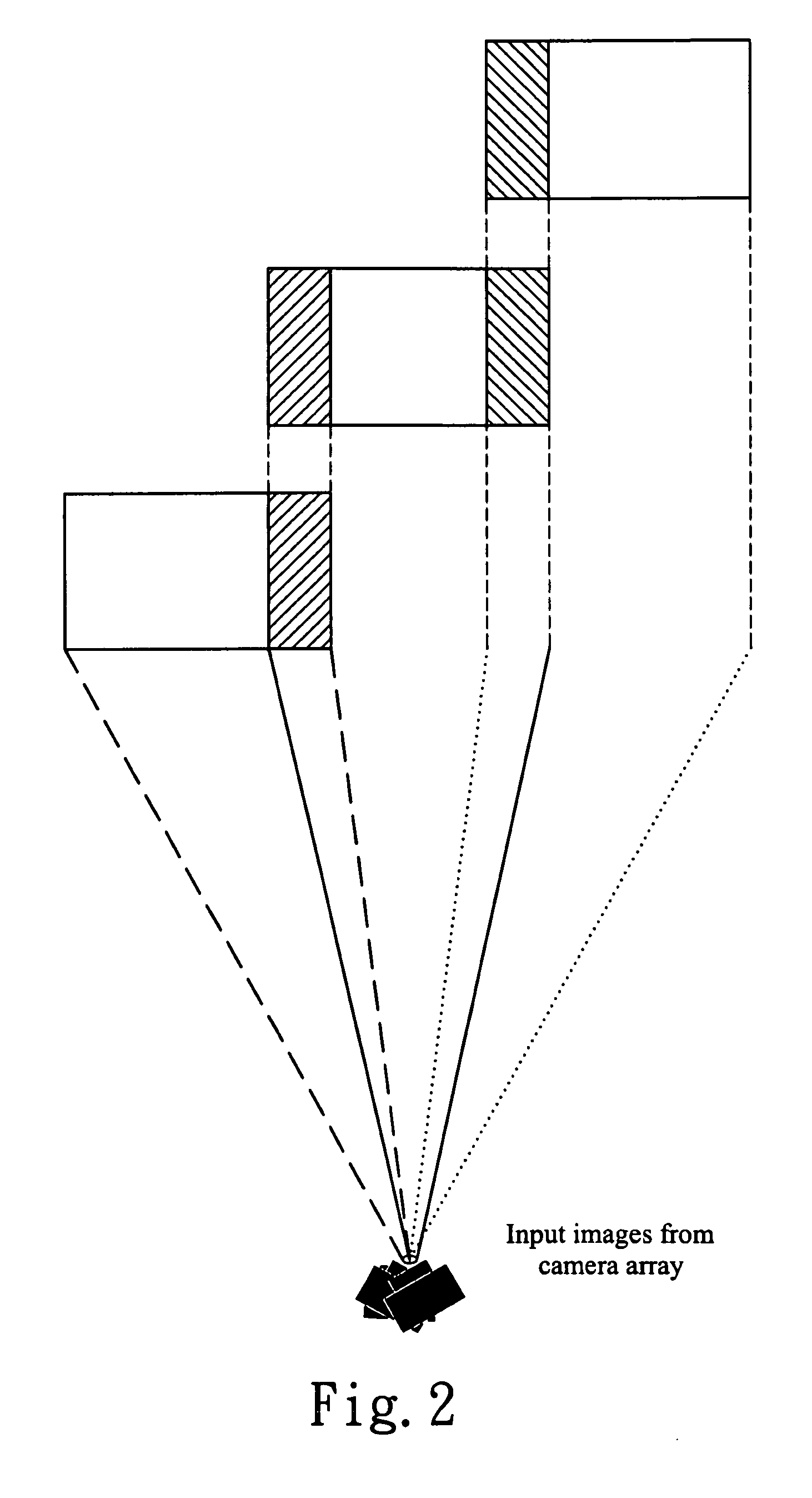
[0013]FIG. 2 shows an input image from the camera array 20. The shaded areas are overlapped regions between side images (from side camera) and center images (from center camera). The overlapped regions are used for feature detection window in the dynamic stitching engine 10. The feature...


PUM


Abstract

An advanced dynamic stitching method for multi-lens camera system is disclosed. This invention aims to address the parallax phenomenon which exists in a multi-lens camera system. Stitching points vary with the object distance. In a video stitching system, a fast search engine to update the stitching points dynamically is needed. This invention provides an advanced method to reduce the high computation power required for the traditional block matching method of finding stitching points. As a result, the stitching points can be adjusted dynamically with the method of this invention.

Description

BACKGROUND OF THE INVENTION[0001]This invention relates to a multi-lens camera system, and more particularly, to a parallax phenomenon of an advanced dynamic stitching method for multi-lens camera system.DESCRIPTION OF RELATED ART[0002]A multi-lens camera system as claimed in US Patent No. US2004 / 0201769 A1 uses an optical method to suppress the parallax phenomenon. In the optical method, the lens sets must be put on an exact position. Otherwise the parallax between images will be showed up. It is still necessary to implement a fast stitching point searching engine in video stitching engine to dynamically adjust the stitching point due to the changes in object distance.SUMMARY OF THE INVENTION[0003]Accordingly, the present invention provides a fast and effective search engine to update stitching points dynamically so that the parallax phenomenon can be compensated.[0004]A multi-lens camera system is consisted of several single lens cameras which face to different directions. In orde...

Claims


Application Information

Patent Timeline
Patent Type & Authority Applications(United States)
IPC IPC(8): H04N5/225
CPCH04N5/232G03B37/04H04N5/2624H04N5/23238H04N23/698
Inventor PAN, PATRICK
Owner SONY TAIWAN
Learn More