Method and apparatus for coding moving image and imaging system

Inactive Publication Date: 2009-02-26
PANASONIC CORP
View PDF10 Cites 8 Cited by
  • Summary
  • Abstract
  • Description
  • Claims
  • Application Information

AI Technical Summary

Benefits of technology

[0010]It is therefore an object of the present invention to generate coded streams associated with a larger number of moving image signals, without increase in power consumption and circuit scale of moving image coding apparatus.
[0012]With this moving image coding method, a plurality of coded streams associated with a plurality of moving image signals are generated from one moving image signal without individually coding the moving image signals. Accordingly, coded streams associated with a larger number of moving image signals than that with conventional methods are generated without increase in power consumption and circuit scale of moving image coding apparatus.
[0020]In this moving image coding apparatus, a plurality of coded streams associated with a plurality of moving image signals are generated from one moving image signal without individually coding the moving image signals. Accordingly, coded streams associated with a larger number of moving image signals than in conventional apparatus are generated without increase in power consumption and circuit scale of the moving image coding apparatus. As a result, reduction in size and power consumption of moving image coding apparatus is achieved.

Problems solved by technology

Thus, studies for reducing size and power consumption of this technique are also intensively carried out.
However, the foregoing moving image coding apparatus has limitations in its processing performance.
Accordingly, enhancement of function and performance of moving image coding apparatus disadvantageously increases power consumption and circuit scale of the moving image coding apparatus, thus making it difficult to reduce the size and power consumption of the apparatus.

Method used


Image

  • Method and apparatus for coding moving image and imaging system
  • Method and apparatus for coding moving image and imaging system
  • Method and apparatus for coding moving image and imaging system

Examples


embodiment 1

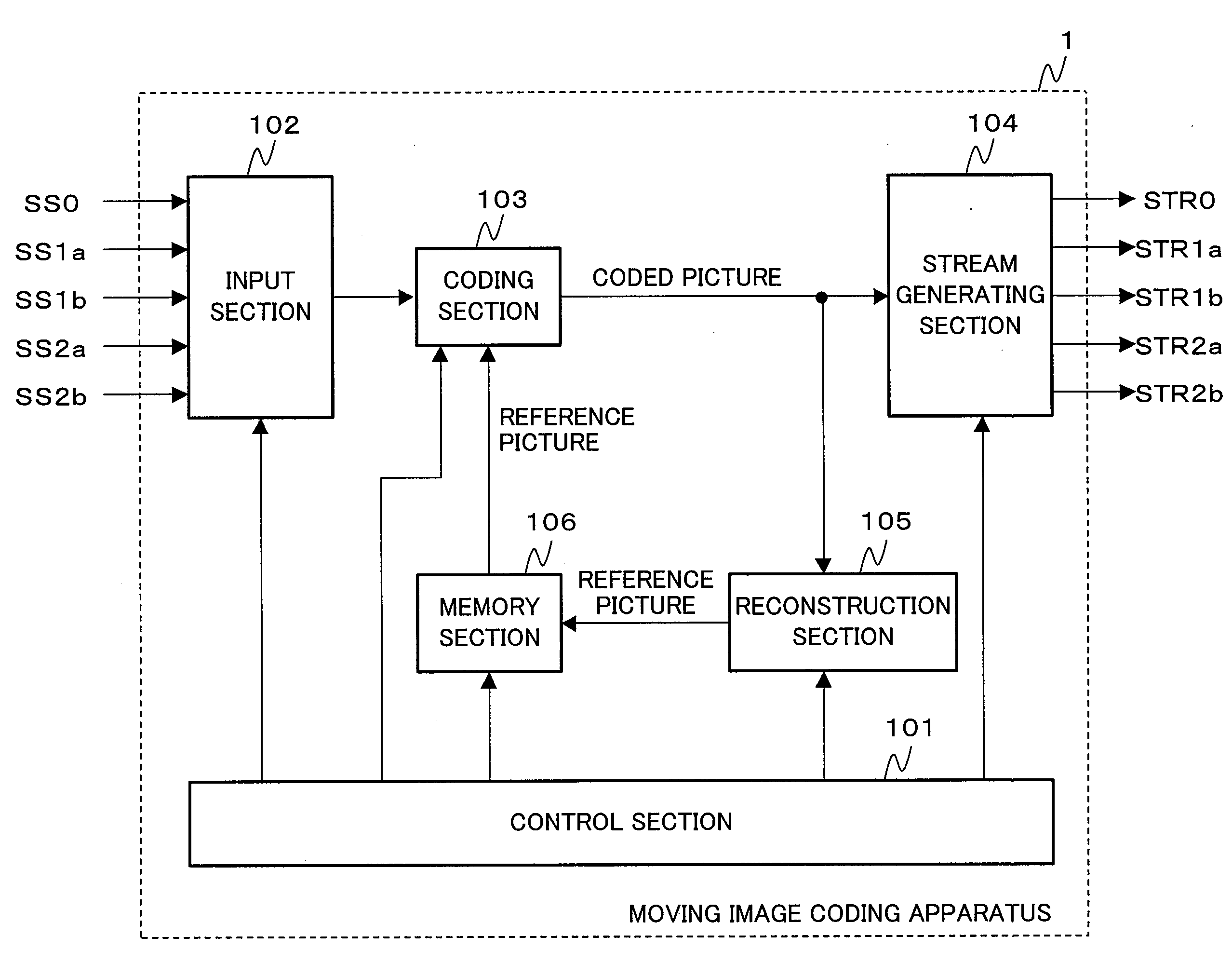
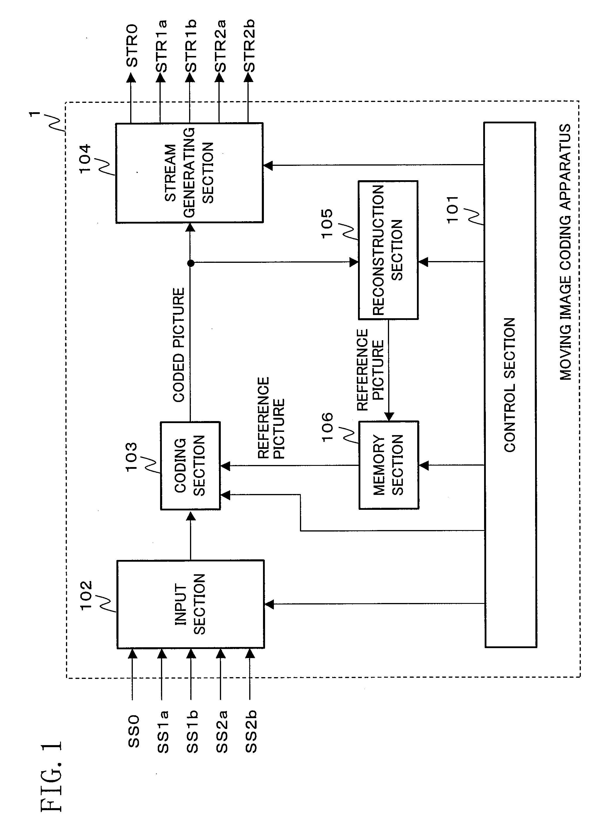
[0034]FIG. 1 illustrates a configuration of moving image coding apparatus according to a first embodiment of the present invention. In the moving image coding apparatus 1, channels are respectively allocated to a plurality of moving image signals (which are five moving image signals SS0 to SS2b in this embodiment) and the moving image signals are coded in a time-division manner on a picture-by-picture basis, thereby generating a plurality of coded streams (which are five coded streams STR0 to STR2b in this embodiment) associated with the moving image signals. The moving image coding apparatus 1 includes: a control section 101; an input section 102; a coding section 103; a stream generating section 104; a reconstruction section 105; and a memory section 106.

[0035]The control section 101 controls the input section 102, the coding section 103, the stream generating section 104, the reconstruction section 105 and the memory section 106. The control section 101 determines settings of cod...

modified example 1 of embodiment 1

[0090]During inter-coding by the coding section 103, the time difference between a picture as a target of coding and a reference picture increases, the correlation between these pictures becomes lower so that the difference between the picture as a target of coding and the reference picture is likely to increase. In particular, when a picture as a target of coding exhibits a fast motion, the correlation between the pictures greatly decreases. For example, when the picture P1(1) and the picture P2(1) in FIG. 4 are compared with each other, the coding efficiency in inter-coding of the picture P2(1) is more likely to decrease than that in inter-coding of the picture P1(1).

[0091]In view of this, as shown in FIG. 7A, the value of a quantization parameter used for coding of pictures may be adjusted based on the time difference between a picture as a target of coding and a reference picture. Specifically, the control section 101 determines whether or not the time difference between a pictu...

modified example 2 of embodiment 1

[0093]As shown in FIG. 7B, a motion search range used for inter-coding of pictures may be adjusted based on the time difference between a picture as a target of coding and a reference picture. Specifically, the control section 101 determines whether or not the time difference between a picture supplied from the input section 102 to the coding section 103 and a reference picture associated with this picture is larger than a given value (step ST120). If it is determined that the time difference is larger than the given value, the control section 101 extends a motion search range set in the coding section 103 (step ST122). For example, if the motion search range before the adjustment is −32 to +32 in the horizontal and vertical directions, the motion search range is extended to −64 to +64 in the horizontal and vertical directions.

[0094]With this control, a position exhibiting a high correlation between pictures is more easily detected from pictures as a target of coding, thus suppressi...


PUM


Abstract

A moving image signal is coded so that a coded stream is generated. Coded pictures are periodically eliminated from the coded moving image signal so that another coded stream associated with another moving image signal having a frame rate different from the coded moving image signal is generated.

Description

BACKGROUND OF THE INVENTION[0001]The present invention relates to a technique for coding moving image signals into coded streams.[0002]In recent years, highly-efficient coding techniques for processing moving images such as MPEG-4, H.264 (MPEG-4 AVC) including MPEG-2 have been intensively studied to be applied to various fields such as computers, communication, consumer AV equipment and broadcasting. In particular, to provide consumer cameras such as video or digital still cameras at low cost, it is very important to implement a moving image coding technique for processing an enormous amount of data in a small size with low power consumption. Thus, studies for reducing size and power consumption of this technique are also intensively carried out. For transmission camera equipment such as a network camera with which coded streams (i.e., compressed data of moving images) are transmitted via a communication line such as the Internet, a plurality of moving image signals with different r...

Claims


Application Information

Patent Timeline
IPC IPC(8): H04N7/24
CPCH04N21/234381H04N21/4436H04N19/61H04N19/124H04N19/40H04N19/156H04N19/57H04N19/587H04N19/132
Inventor KITAMURA, SHINJI
Owner PANASONIC CORP
Why Eureka
Try Eureka