Imaging cartridge and image forming apparatus

a technology image cartridge, which is applied in the field of image forming apparatus, can solve the problems of increasing the total cost of ownership (tco), complicated replacement procedures, etc., and achieves the effects of reducing tco, improving setting property and positioning accuracy, and simplifying replacement procedures

Inactive Publication Date: 2009-02-26
KONICA MINOLTA BUSINESS TECH INC
View PDF5 Cites 27 Cited by
  • Summary
  • Abstract
  • Description
  • Claims
  • Application Information

AI Technical Summary

Benefits of technology

[0007]Accordingly, an object of the present invention is to provide an imaging cartridge having a new toner box and a waste toner box in a detachable manner and enabled to achieve successful setting property and high positioning accuracy of the new toner box and the waste toner box.
[0010]Since there is provided a toner replenishment type imaging cartridge having the new toner box and the waste toner box which can be attached to and detached from the process unit, the process unit generally including expensive components can be used as long as possible, thereby allowing reduction in TCO.
[0011]Moreover, since the new toner box and the waste toner box are detachably attached to the process unit, the attaching and detaching procedures of the new toner box and the waste toner box, which are consumable items, to / from the image forming apparatus body are simple and easy to understand.
[0012]The new toner box and the waste toner box are coupled to each other by the support mechanism in a manner allowing elastic relative displacement so as to support each other. Accordingly, when the imaging cartridge is loaded into the image forming apparatus body, at least one of the new toner box and the waste toner box is enabled to retreat from an original position, so that successful setting property of the new toner box and the waste toner box onto the image forming apparatus body is achieved.
[0013]Also, the new toner box and the waste toner box are elastically displaceable relative to each other by the support mechanism, and the elastic pressing force exerted by the support mechanism on the new toner box and the waste toner box contributes to their positioning with respect to the process unit. Therefore, the new toner box and the waste toner box are positioned with respect to the process unit with high degree of accuracy, which leads to stabilization of imaging quality.
[0015]According to the imaging cartridge in the present invention, it becomes possible to accomplish both the simplification of replacement procedures of the new toner box and the waste toner box, which are consumable items, and the reduction in TCO, while accomplishing improvement in the setting property and the positioning accuracy of the new toner box and the waste toner box, simplification of the mechanism of the image forming apparatus body, reduction in loss of the pressing force to the developing device, and the like.

Problems solved by technology

However, the first and third aspects increase the number of consumable items, resulting in complicates replacement procedures.
Further, the second aspect requires replacement of the imaging cartridge for such reasons as exhaustion of the toner in the new toner box (toner empty) and the waste toner filling of the waste toner box (waste toner full) even if expensive components included in the imaging cartridge have not yet expired in life, thereby causing increase in total cost for ownership (TCO).

Method used


Image

  • Imaging cartridge and image forming apparatus
  • Imaging cartridge and image forming apparatus
  • Imaging cartridge and image forming apparatus

Examples


first embodiment

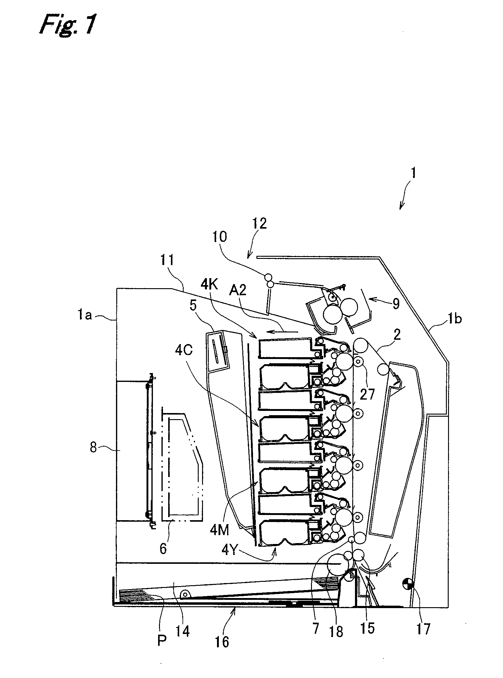
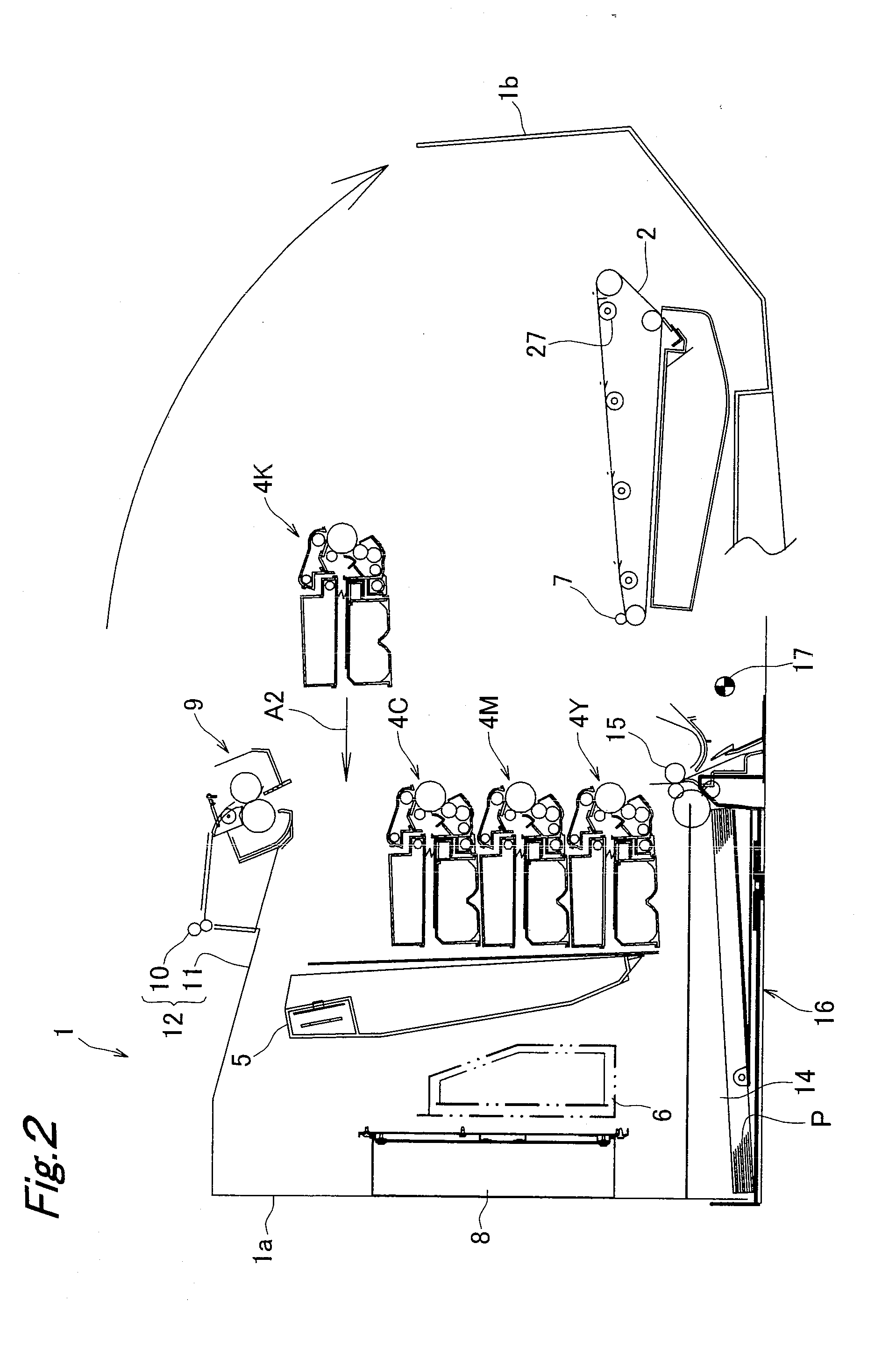
[0038]FIG. 1 shows an image forming apparatus (tandem-type color laser printer) 1 having an imaging cartridge according to a first embodiment of the present invention.

[0039]Arranged inside an apparatus main frame 1a of the image forming apparatus 1 is a transfer belt 2 stretched over a plurality of rollers. Also in the apparatus main frame 1a, four imaging cartridges 4Y, 4M, 4C and 4K of yellow, magenta, cyan and black are arranged in the longitudinal direction on a rear-face side of the apparatus main frame 1a (left-hand side in FIG. 1) with respect to the transfer belt 2. Further, accommodated in the apparatus main frame 1a on a further rear-face side from the imaging cartridges 4Y to 4K are, a laser exposure device 5, an electric power unit 6 for supplying electric power to the entire apparatus, and a control device 8 for controlling operation of each section. Placed on an upper side of the apparatus main frame 1a are a fixing device 9 and a paper ejection device 12 composed of a...

second embodiment

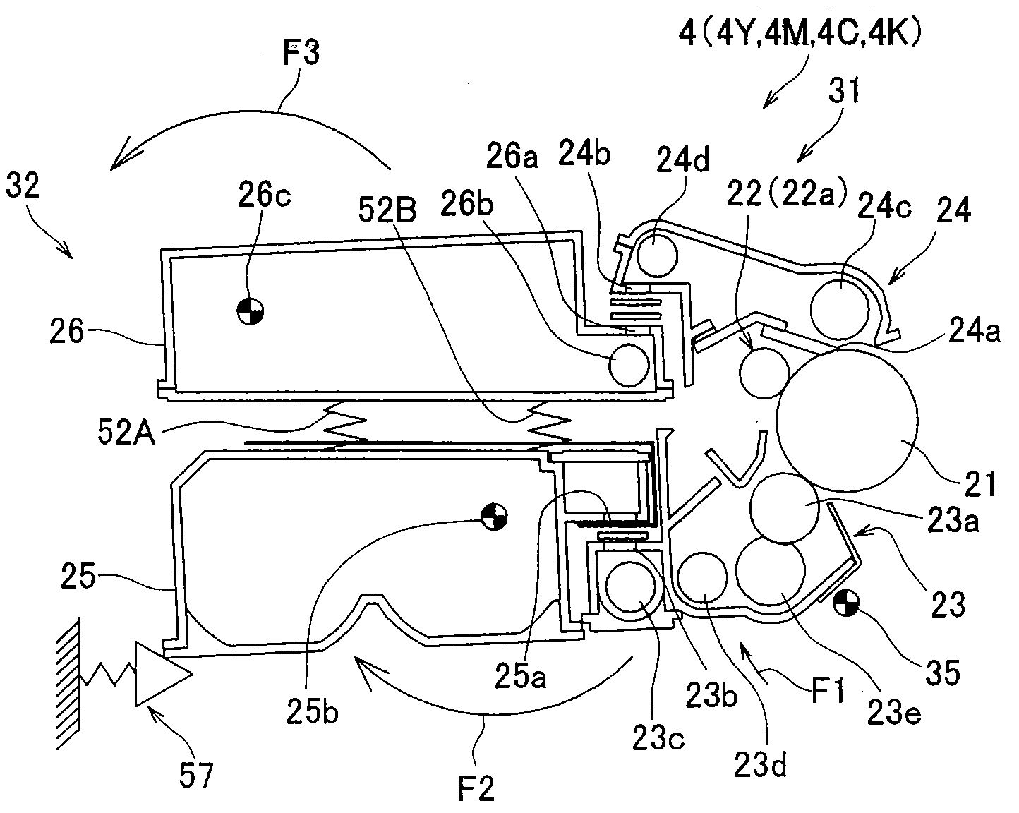
[0066]FIG. 12 to FIG. 15 show an imaging cartridge 4 according to a second embodiment of the present invention. In the present embodiment, a plurality of pressing mechanisms 57 and 62 are provided on the apparatus main frame 1a side.

[0067]As most clearly shown in FIGS. 12 and 14, a development side rotating pivot 25b of the new toner box 25 is provided in the portion adjacent to the development side toner delivery opening 25a (portion on the insertion section 38 side) and the waste side rotating pivot 26c of the waste toner box 26 is provided in a portion adjacent to the waste side toner reception opening 26a (portion on the insertion section 38 side). As shown in FIG. 12, FIG. 13, and FIG. 15, on the apparatus main frame 1a side, a second pressing mechanism 62 for elastically biasing the waste toner box 26 is provided above the first pressing mechanism 57 for elastically biasing the new toner box 25. The structure of the second pressing mechanism 62 is identical to that of the firs...

third embodiment

[0074]An imaging cartridge 4 according to a third embodiment of the present invention shown in FIGS. 17 and 18 is different in the structure of the support mechanism 51 from the second embodiment. More specifically, whereas the support mechanism 51 in the second embodiment couples the new toner box 25 and the waste toner box 26 to each other in an unremovable manner, a support mechanism 51 in the present embodiment couples the new toner box 25 and waste toner box 26 to each other in a removable or detachable manner.

[0075]The lower end sides of the helical compression springs 52A and 52B are coupled to the upper surface of the new toner box 25, while the upper end sides thereof are coupled to a pair of guide rails 64. Each of the guide rails 64 extends in the inserting direction into the process unit 31 (see the arrow “A1” in FIGS. 11 and 16), and is elastically displaceable in vertical direction. Provided on the lower surface of the waste toner box 26 is guide projections 65 which e...


PUM


Abstract

An imaging cartridge is detachably loaded into an image forming apparatus body. A process unit has a developing device for developing an electrostatic latent image on a photoconductor to form a toner image, and a cleaning device for collecting toner remaining on the image bearing body even after transfer of the toner image. A new toner box is detachably attached to the process unit and serves for storing therein unused toner fed to a developing device. A waste toner box is detachably attached to the process unit and serves for storing therein waste toner collected by the cleaning device. A support mechanism couples the new toner box and the waste toner box to each other so as to be supported each other in a manner allowing elastic relative displacement.

Description

RELATED APPLICATION[0001]This application based on Japanese Patent Application No. 2007-216670 the contents in which are incorporated herein by reference.BACKGROUND OF THE INVENTION[0002]The present invention relates to an imaging cartridge used for image forming apparatuses such as copying machines, facsimile machines, printers, and multi-functional machines.[0003]For enhancing maintenanceability, an imaging cartridge has been known which can be loaded into and unloaded from an image forming apparatus body by providing such devices as an image bearing body, a charging device, a developing device, a transfer device, a cleaning device in the form of cartridges (see, e.g., Japanese Patent Application Laid-Open Publication 2006-267922). In this kind of imaging cartridge, with respect to a new toner box for storing unused toner to be fed to the developing device and a waste toner box for storing waste toner collected by the cleaning device, the following three aspects are generally know...

Claims


Application Information

Patent Timeline
Patent Type & Authority Applications(United States)
IPC IPC(8): G03G15/08
CPCG03G21/12G03G2215/0685G03G2221/1624G03G15/0868G03G2221/1815G03G2221/1861G03G15/0875G03G2221/1654
Inventor MIZUNO, HIROSHIKUGIMIYA, ISAMUHASHIMOTO, TAKESHIYOSHIDA, NAOTOKONDO, NOZOMU
Owner KONICA MINOLTA BUSINESS TECH INC
Why Eureka
Try Eureka