Stackable composite power connector

Inactive Publication Date: 2009-02-26
DELTA ELECTRONICS INC
View PDF7 Cites 21 Cited by
  • Summary
  • Abstract
  • Description
  • Claims
  • Application Information

AI Technical Summary

Benefits of technology

[0008]It is an object of the present invention to provide a stackable composite power connecto

Problems solved by technology

In a case that the UPS apparatus has a plurality of batteries, the wire linkages become complicated because man

Method used


Image

  • Stackable composite power connector
  • Stackable composite power connector
  • Stackable composite power connector

Examples


Embodiment Construction

[0015]The present invention will now be described more specifically with reference to the following embodiments. It is to be noted that the following descriptions of preferred embodiments of this invention are presented herein for purpose of illustration and description only. It is not intended to be exhaustive or to be limited to the precise form disclosed.

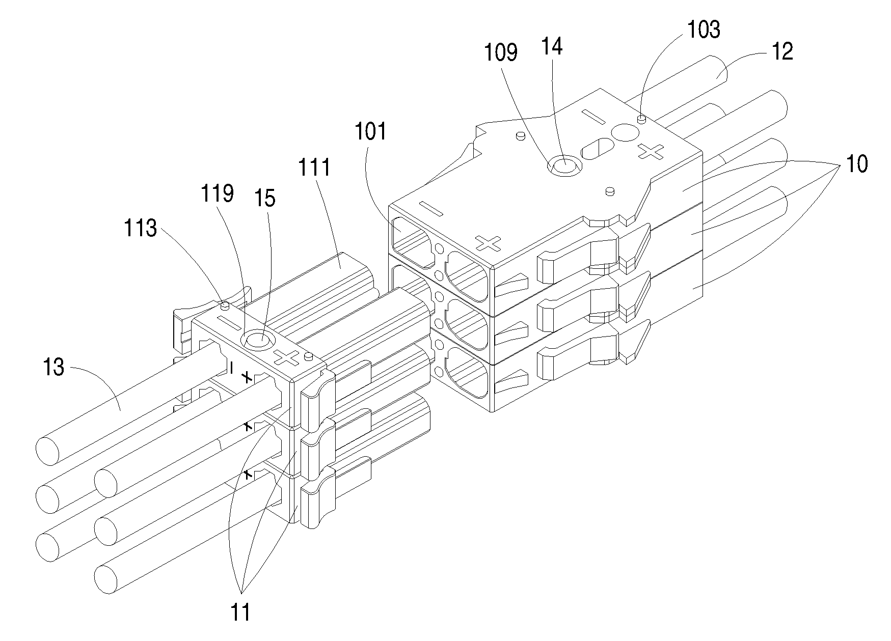
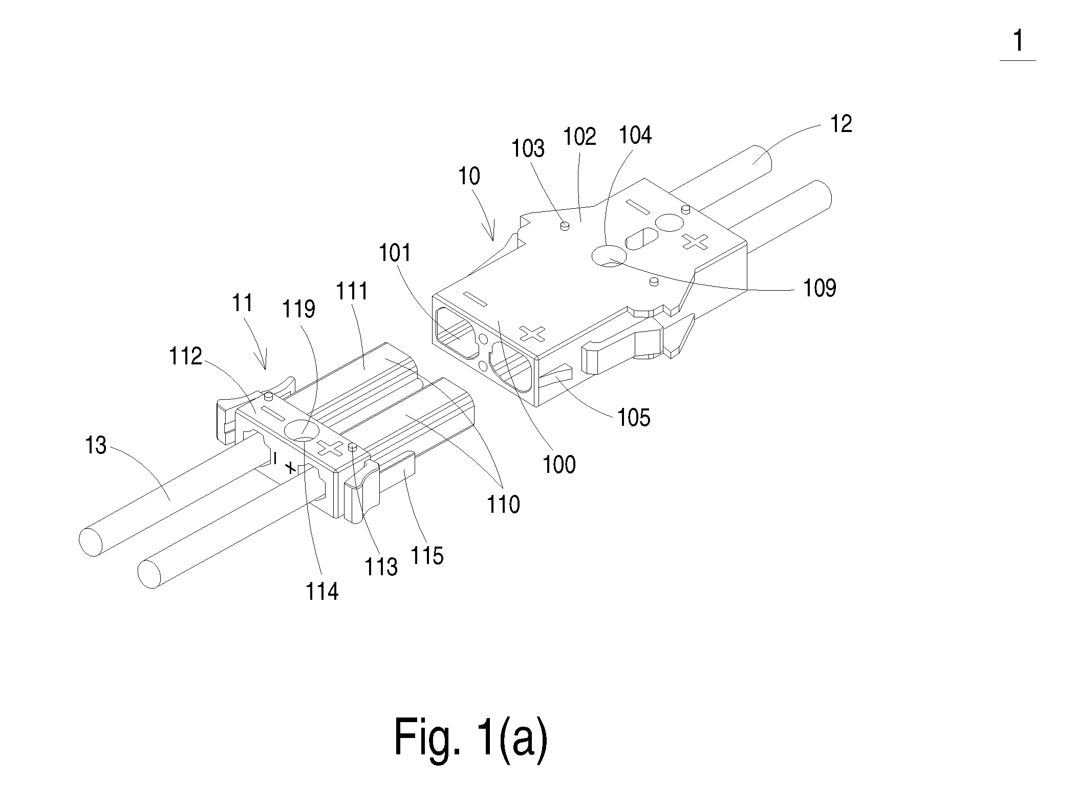
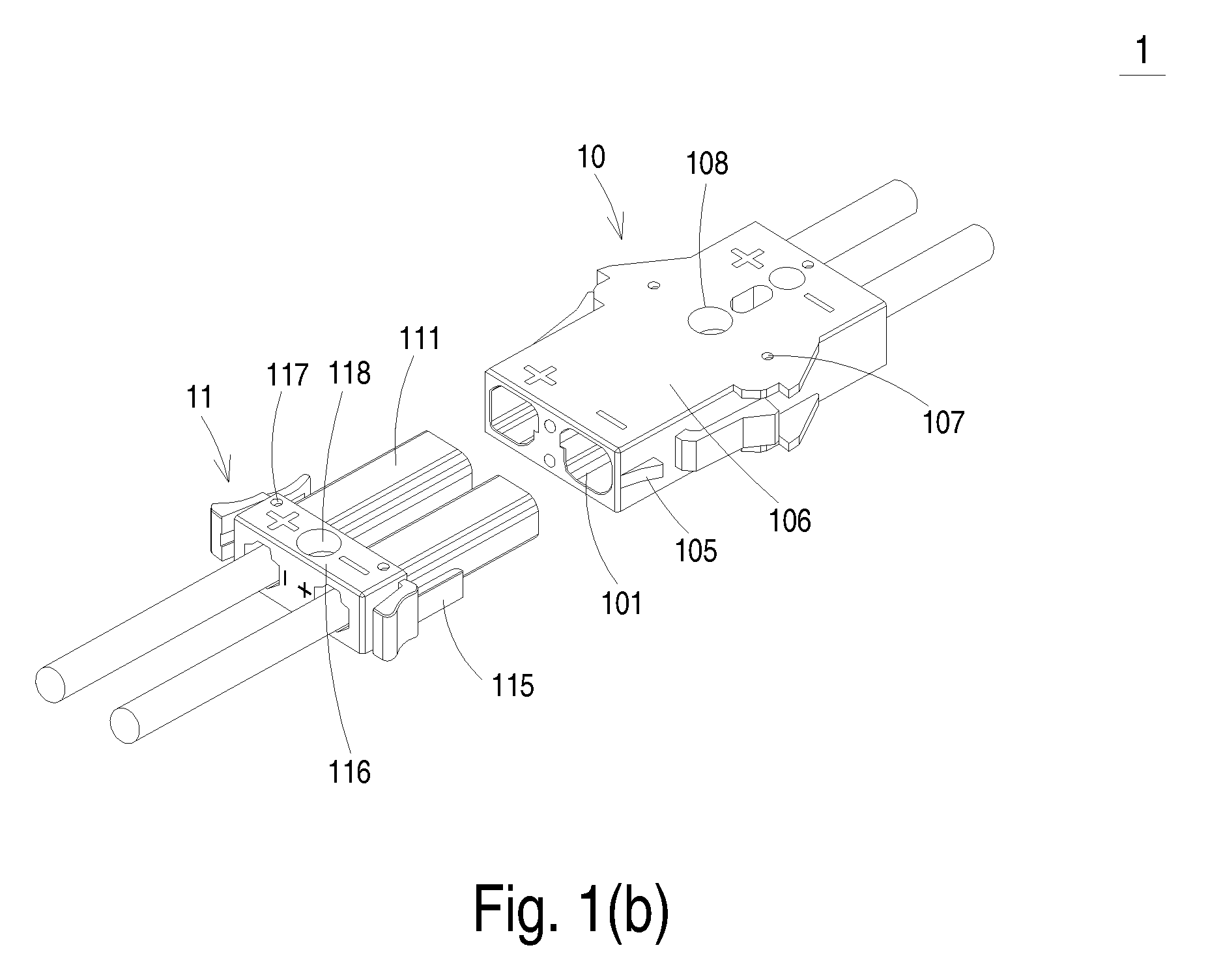
[0016]Referring to FIGS. 1(a) and 1(b), schematic front and backside views of a power connector assembly according to a preferred embodiment of the present invention are respectively illustrated. As shown in FIG. 1(a), the power connector assembly 1 principally includes a first connecting unit 10 and a second connecting unit 11. An end of the first connecting unit 10 is electrically connected to a power-supplying device (not shown) such as a battery of a UPS apparatus via electric wires 12. The other end of the first connecting unit 10 is formed as an insertion terminal 100 to be coupled with the second connecting unit 11. In thi...


PUM


Abstract

The present invention relates to a composite power connector. The composite power connector includes multiple first connecting units arranged in a stack form, multiple second connecting units arranged in a stack form and a fastening element. Each first connecting unit includes a first end coupled with an electric wire, a second end formed as an insertion terminal to be coupled with a corresponding second connecting unit, a first surface having a first perforation and a second surface having a second perforation corresponding to the first perforation. A channel is defined by the first perforation and the second perforation. The fastening element penetrates through the channels of the multiple first connecting units for combining and fixing the multiple first connecting units with each other.

Description

FIELD OF THE INVENTION[0001]The present invention relates to a composite power connector, and more particularly to a stackable composite power connector.BACKGROUND OF THE INVENTION[0002]Various connectors have been broadly used to deliver electric power from power-supplying devices to power-receiving devices. Take an uninterruptible power supply (UPS) apparatus for example. A connector is used to connect the UPS apparatus and a power-receiving device. When the utility power is normally provided, the electronic circuit of the UPS apparatus converts the utility power from alternating current (AC) to direct current (DC) for supplying the power-receiving device and charging a battery contained therein. When the utility power is unavailable, the uninterrupted power supply system converts the electric power stored in the battery so as to continuously supply power to the power-receiving device and avoid power failure.[0003]Generally, an uninterruptible power supply (UPS) system includes a ...

Claims


Application Information

Patent Timeline
IPC IPC(8): H01R25/00
CPCH01R13/514H01R13/64H01R13/6273H01R13/518
Inventor TSOU, YUNG-HUNGHSIEH, TUNG-HUNG
Owner DELTA ELECTRONICS INC
Why Eureka
Try Eureka