Bicycle rear derailleur with a motion resisting structure

a technology of derailleur and rear derailleur, which is applied in the direction of mechanical equipment, transportation and packaging, and gearing, etc., can solve the problem of chain bouncing severely

Active Publication Date: 2009-02-26
SHIMANO INC
View PDF10 Cites 110 Cited by
  • Summary
  • Abstract
  • Description
  • Claims
  • Application Information

AI Technical Summary

Problems solved by technology

When riding on rough terrain, the chain guide sometimes swings both in the chain tensioning direction and in the direction opposite to the chain tensioning direction, thereby causing the chain to bounce severely.

Method used


Image

  • Bicycle rear derailleur with a motion resisting structure
  • Bicycle rear derailleur with a motion resisting structure
  • Bicycle rear derailleur with a motion resisting structure

Examples


Embodiment Construction

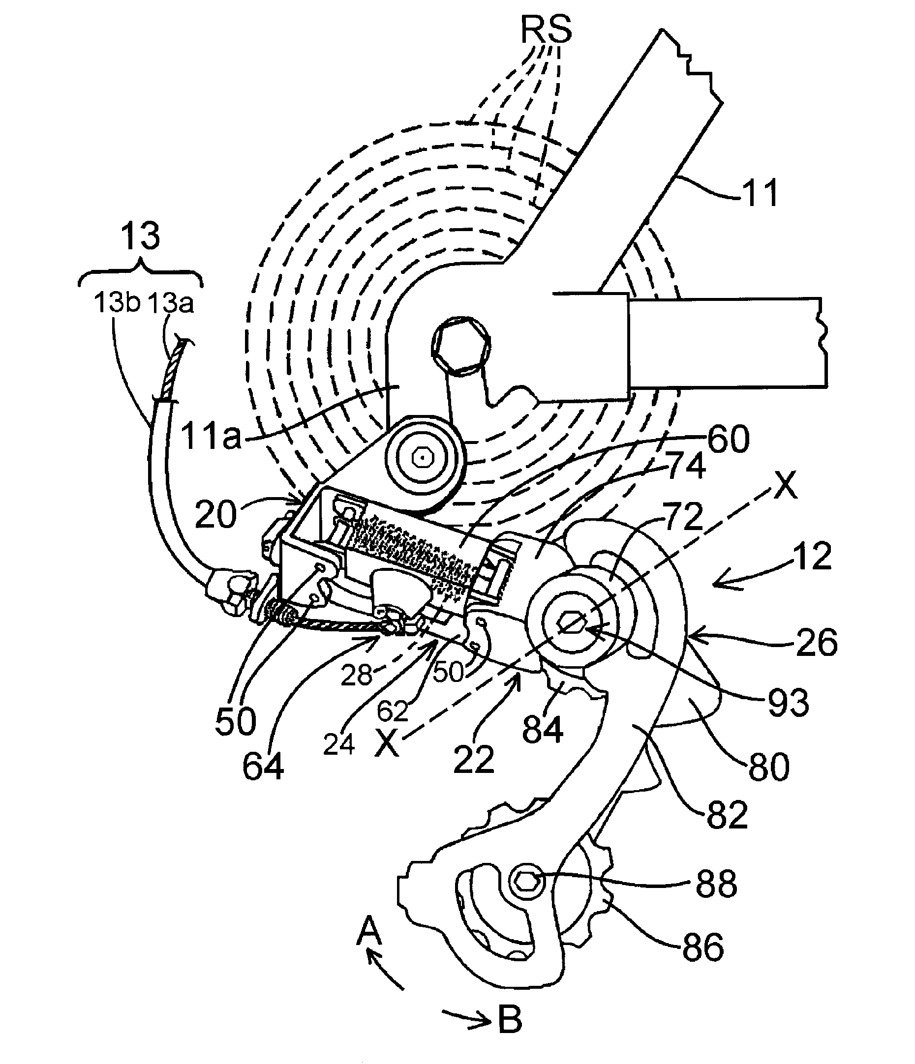
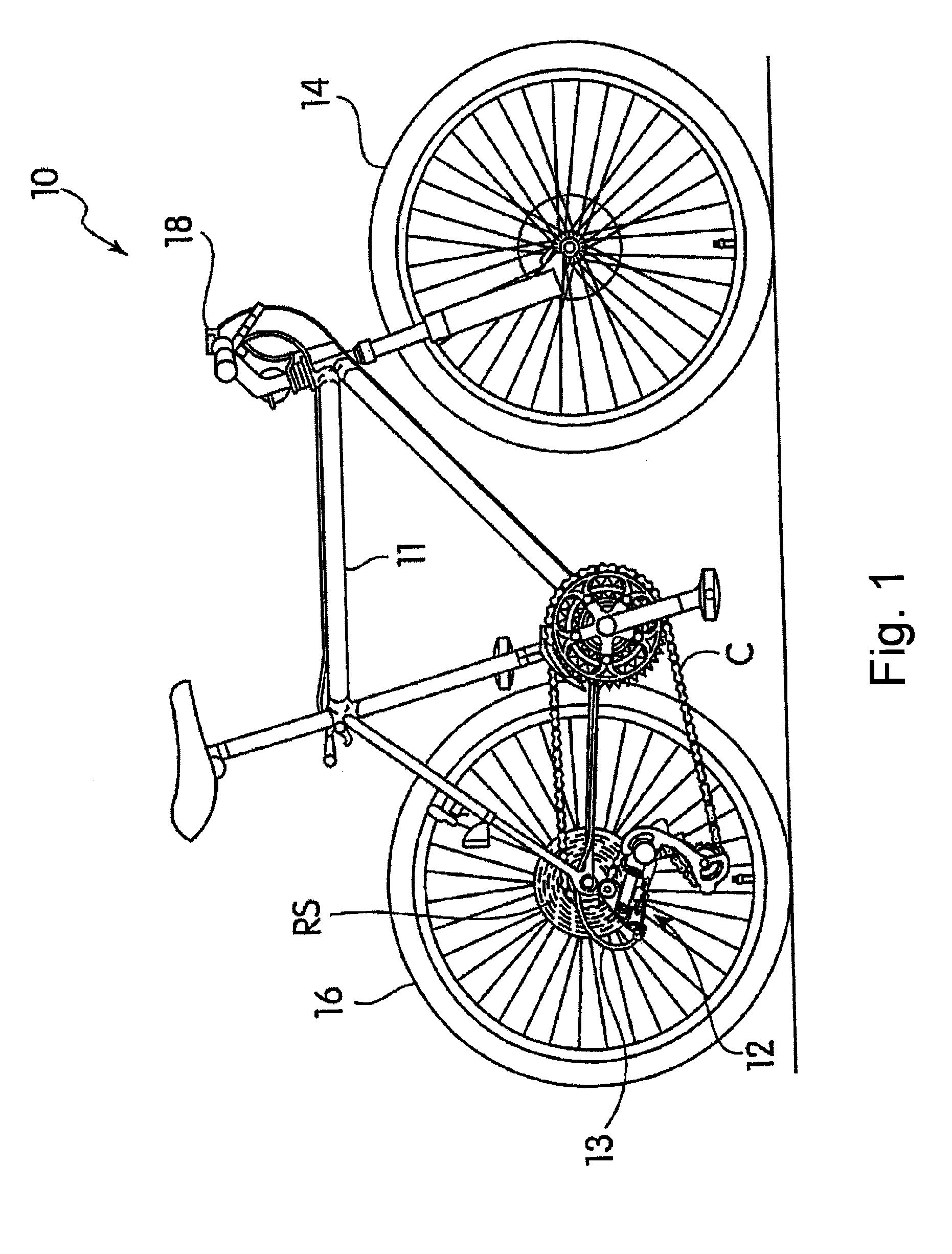
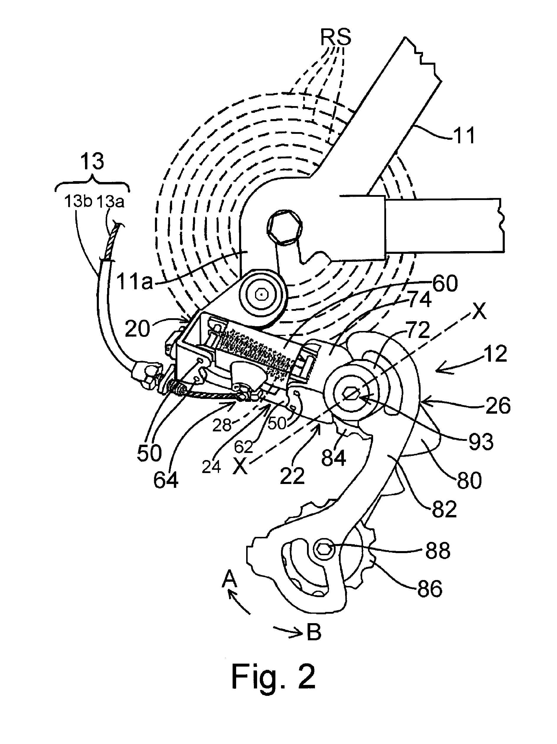
[0016]FIGS. 1 and 2 show a bicycle 10 equipped with a particular embodiment of a rear derailleur 12. Bicycle 10 is a conventional bicycle except for rear derailleur 12, so only rear derailleur 12 will be discussed in detail herein.

[0017]Bicycle 10 comprises a frame 11 with front and rear wheels 14 and 16 rotatably coupled to frame 11 in a conventional manner. The rear of frame 11 includes a rear derailleur mounting plate 11a, and rear derailleur 12 is directly attached to rear derailleur mounting plate 11a. Of course, many different rear derailleur mounting structures can be provided, such as a removable type derailleur hanger (not shown). Bicycle 10 further includes a conventional rear shift control device 18 mounted on a handlebar to control rear derailleur 12 via a Bowden-type shift control cable 13 that includes an inner wire 13a slidably disposed within an outer casing 13b. The rider operates shift control device 18 to selectively pull or release inner wire 13a to operate rear ...


PUM


Abstract

A bicycle derailleur comprises a base member adapted to be mounted to a bicycle, a movable member movably coupled to the base member, and a chain guide coupled to the movable member. The chain guide is coupled for rotation around a rotational axis (X), and a biasing element biases the chain guide in a selected rotational direction. A resistance applying unit applies a resistance to rotational movement of the chain guide in a direction opposite the selected rotational direction, and an adjusting unit adjusts an amount of resistance applied by the resistance applying unit.

Description

BACKGROUND OF THE INVENTION[0001]The present invention is directed to bicycle derailleurs and, more particularly, to a bicycle derailleur with a motion resisting structure.[0002]Bicycling is becoming an increasingly more popular form of recreation as well as a means of transportation. Moreover, bicycling has become a very popular competitive sport for both amateurs and professionals. Whether the bicycle is used for recreation, transportation or competition, the bicycle industry is constantly improving the various components of the bicycle. One component that has been extensively redesigned is the bicycle rear derailleur.[0003]Typically, a rear derailleur comprises a base member, a movable member movably coupled to the base member via a linkage assembly, and a chain guide movably coupled to the movable member. The base member is attached to the frame of the bicycle, and the chain guide is configured to move a chain laterally over a plurality of rear sprockets. A torsion spring biases...

Claims


Application Information

Patent Timeline
Patent Type & Authority Applications(United States)
IPC IPC(8): F16H7/10B62M9/121
CPCB62M9/16B62M9/121B62M9/1248B62M2009/007B62M2009/12406
Inventor TAKACHI, TAKESHIIIZUKA, ATSUSHIHARA, NOBUKATSU
Owner SHIMANO INC
Why Eureka
Try Eureka