Articulating Shaper

a shaper and articulating technology, applied in the field of articulating shapers, can solve the problems of leaving behind tissue fragments, increased bleeding, and higher infection rates, and achieve the effect of customizing the shape of the cavity

Inactive Publication Date: 2009-02-26
SPINEOLOGY
View PDF40 Cites 62 Cited by
  • Summary
  • Abstract
  • Description
  • Claims
  • Application Information

AI Technical Summary

Benefits of technology

[0011]In an embodiment, the present invention comprises a shaper for reaming tissue having a single articulating head operably connected to a shaft. According to one aspect, incremental deployment allows for a unique utility in shaping a cavity suited to the particular morphology, that is, a more customizable cavity shape may be achieved.
[0014]In another embodiment, the shaper may limit input force to prevent shear force failure of distal mechanisms through the use of clutches. One such clutch may be a ball detent clutch that may employ a spring force multiplier fulcrum arm. The ball detent clutch may include an internal rod connected to a female ball detent groove. The ball detent may act as a slip clutch using a fulcrum to decrease the height and multiply the spring force. The clutch may utilize materials with low yield point and fracture loads to limit input forces. According to one aspect the clutch may use spring force and cam angles to limit input forces. In yet another embodiment, the clutching device may include a spring that determines the break away force.

Problems solved by technology

The use of rongeurs and curettes tends to leave behind fragments of tissue.
Further, because these rongeurs and curettes require multiple passes, the operation may be prolonged, possibly leading to increased bleeding and higher infection rates.
An open section in the middle of the beam helps reduce this movement, but does not effectively eliminate the unwanted movement.

Method used


Image

  • Articulating Shaper
  • Articulating Shaper
  • Articulating Shaper

Examples


Embodiment Construction

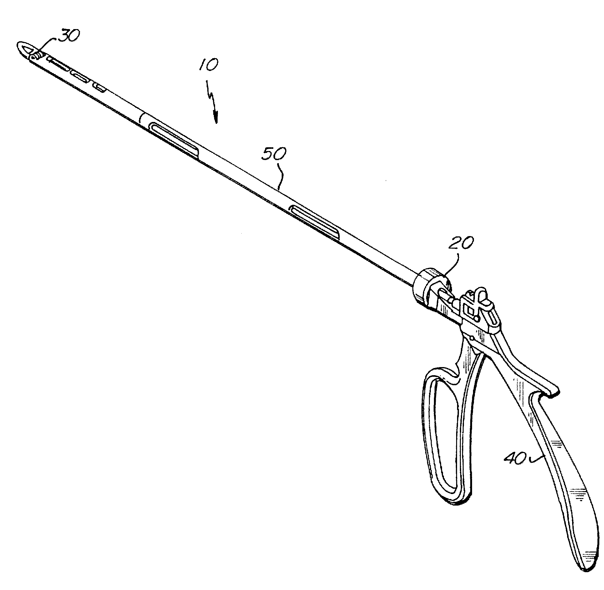
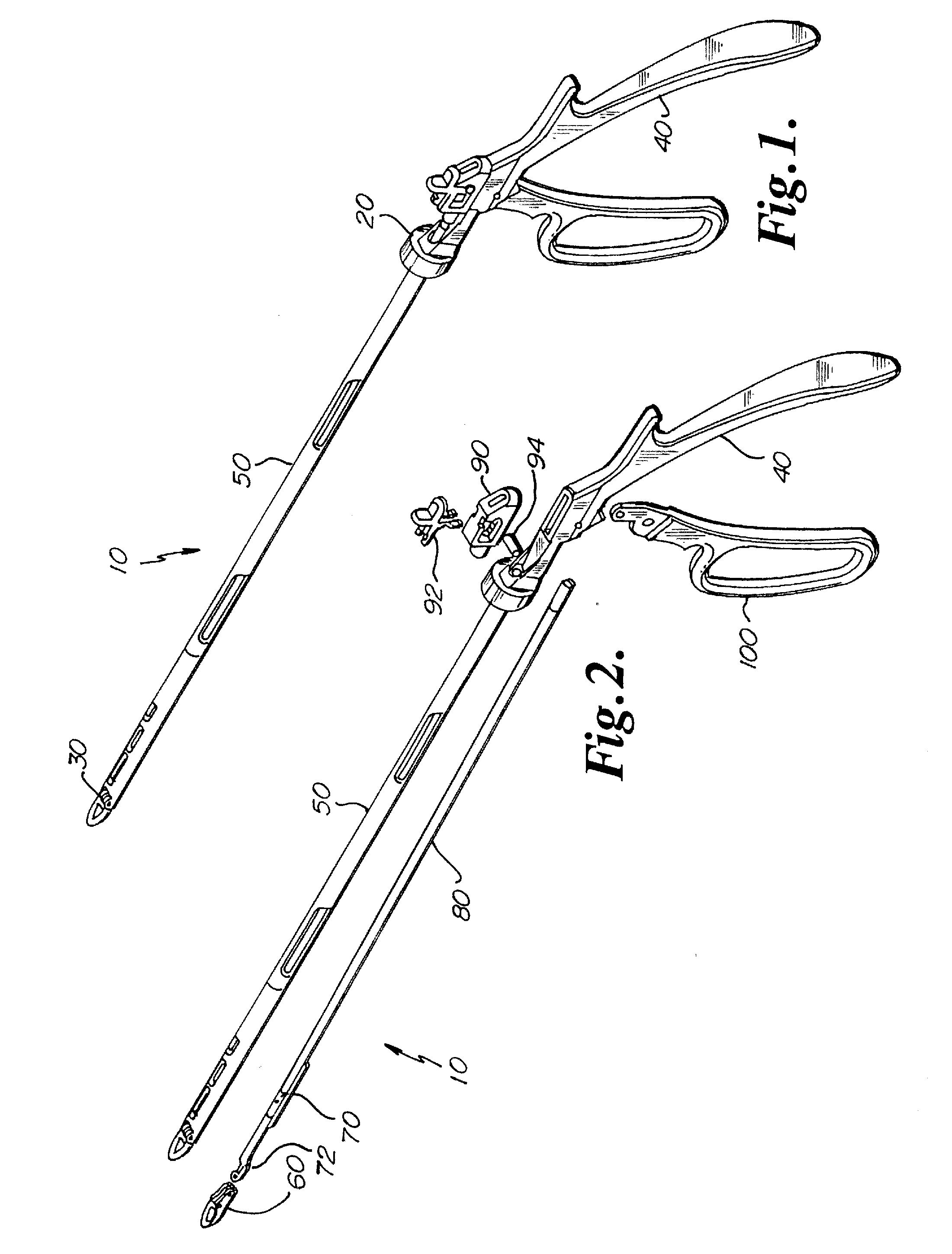
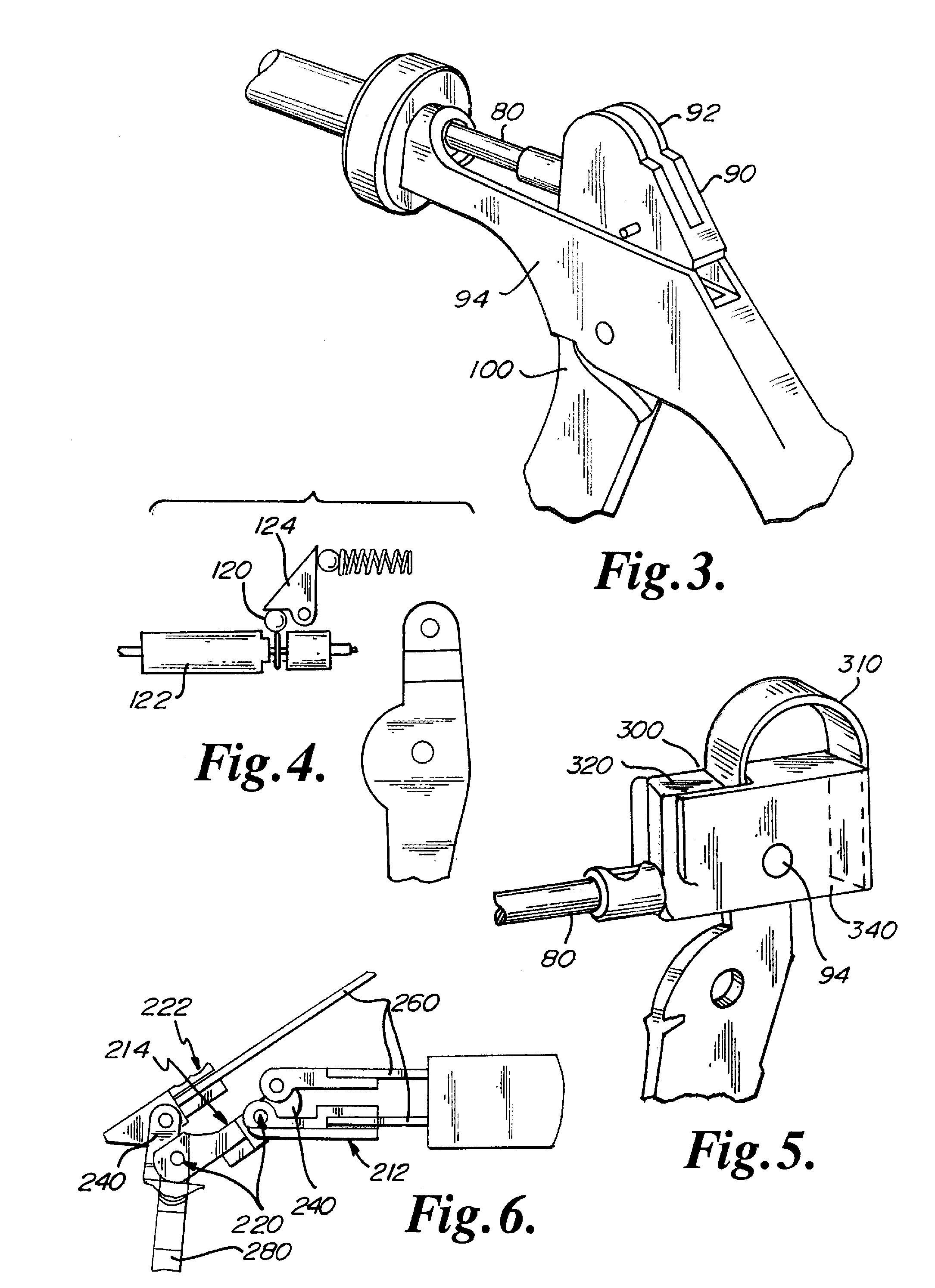
[0027]Referring to FIG. 1 there can be seen a shaper 10 according to one aspect of the present invention. Shaper 10 may include a proximal end 20 and a distal end 30. Shaper 10 may further include a handle 40 and a shaft 50. Referring now to FIG. 2, it can be seen that a cutting head 60 may be operably engaged to distal end 30. Cutting head 60 may be a single articulating head. In an embodiment cutting head 60 may be a blade. In one preferred embodiment, cutting head 60 may be operably connected to spring bar 70 and shaft 50. In an embodiment, cutting head 60 may be pivotally connected to spring bar 70 and shaft 50. Spring bar 70 may be operably connected to a driving rod 80 that is operably connected to a clutch box 90. Clutch box 90 may be actuated by a handle lever 100. Spring bar 70 may be adjacent to cutting head 60 such that driving rod 80 may remain concentric to shaft 50. Spring bar 70 may be operably connected to an offset lever arm 72. Offset lever arm 72 may be activated ...


PUM


Abstract

A shaper for reaming tissue includes an articulating head operably connected to a shaft. Incremental deployment allows for a unique utility in shaping a cavity suited to the particular morphology, that is, a more customizable cavity shape may be achieved.

Description

RELATED APPLICATION[0001]This application claims the benefit of U.S. Provisional Application No. 60 / 919,983 filed Mar. 26, 2007, which is hereby fully incorporated herein by reference.FIELD OF THE INVENTION[0002]This invention relates to an apparatus and method for removing, reaming, debriding and / or resecting tissue and / or bone. In particular, the present invention is directed to a shaper that may be incrementally deployed to create a variety of cavity shapes. The apparatus and method of the present invention may be especially useful in medical procedures such as orthopedic surgery.BACKGROUND[0003]Medical procedures involving the removal of tissue from a region of a body are well known in the art. The present invention may be particularly useful in spine surgery. A variety of tools are available for surgeons to remove spinal disc tissue and / or bony tissue during surgery in the spinal region.[0004]Pituitary rongeurs and curettes are the most frequently used instruments to remove tis...

Claims


Application Information

Patent Timeline
Patent Type & Authority Applications(United States)
IPC IPC(8): A61B17/00
CPCA61B17/1611A61B17/1671A61B17/320725A61B19/30A61B2019/301A61B2017/2919A61B2017/292A61B2017/2925A61B2017/2913A61B90/03A61B2090/031
Inventor GLEASON, JOE
Owner SPINEOLOGY
Why Eureka
Try Eureka