System for Dynamically Controlling the Torque Output of a Pneumatic Tool

a dynamic control and torque output technology, applied in the direction of adaptive control, screws, instruments, etc., can solve the problems of difficult control of the tightening process, very high torque to weight ratio of tools, and very low reaction torque,

Active Publication Date: 2009-02-26
INNOVATION PLUS
View PDF69 Cites 19 Cited by
  • Summary
  • Abstract
  • Description
  • Claims
  • Application Information

AI Technical Summary

Benefits of technology

[0006]A primary objective of the present invention is to eliminate the above-mentioned undesirable characteristics of

Problems solved by technology

Such tools provide very high torque to weight ratios, are very fast and have very low reaction torque since they effectively hammer the bolt tight.
Unfortunately, however, the impacting action of the tools makes it difficult to control the tightening process since it is not possible to make accurate torque measurements, as it is with continuously operating tools.
Consequently, such tools are rarely used in critical applications where bolts are required to be tightened precisely to a specified load or torque.
Certain characteristics associated with impact and impulse tools, however, make them less desirable for use in critical applications.
Firstly, if the tools are sized to tighten bolts quickly, to minimize assembly time, the angl

Method used


Image

  • System for Dynamically Controlling the Torque Output of a Pneumatic Tool
  • System for Dynamically Controlling the Torque Output of a Pneumatic Tool

Examples


Embodiment Construction

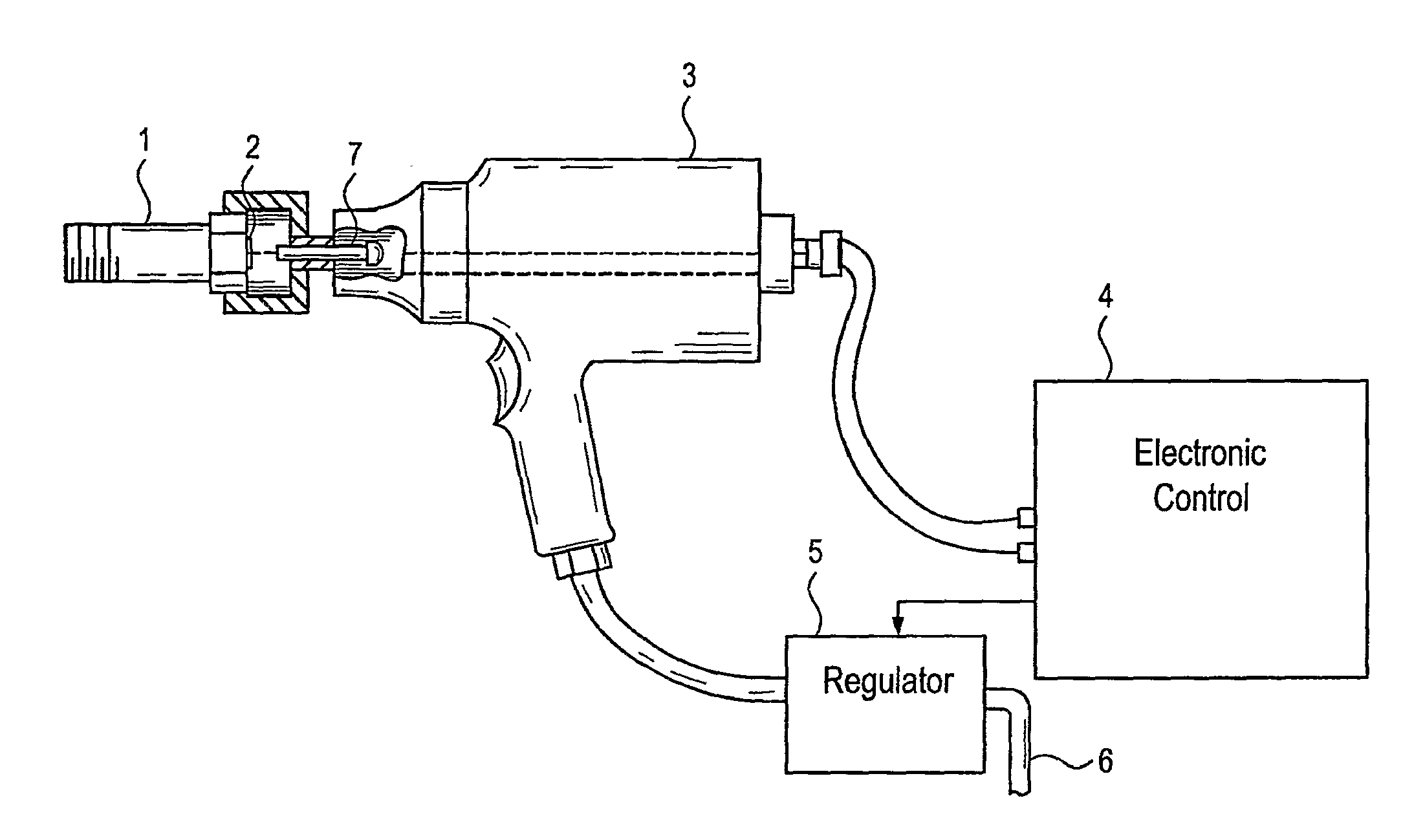
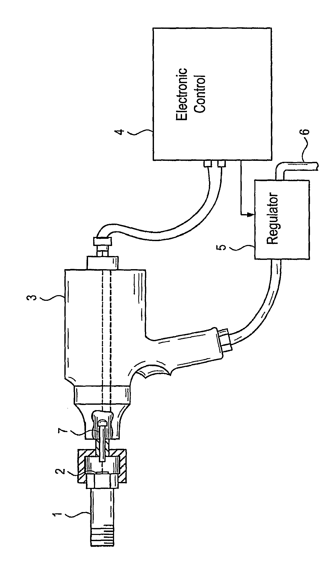
[0012]Referring to the single FIGURE provided, a preferred embodiment of the present invention generally includes a fastener 1 which has been fitted with an ultrasonic transducer 2, a tool such as the illustrated impact wrench 3 which has been modified to measure load in the fastener 1 during tightening using the ultrasonic transducer 2, an electronic control 4 for making load measurements in the fastener 1 and for making control decisions based on the load measurements which have been made, and an electronically controlled air pressure regulator 5 associated with the supply line 6 which delivers pressurized air to the impact wrench 3 to dynamically control the air pressure supplied to the impact wrench 3 during tightening and to stop the impact wrench 3 by reducing the supplied air pressure to zero.

[0013]The fastener 1 of the preferred embodiment of the present invention is preferably a load indicating fastener with a permanent ultrasonic transducer 2, such as is described, for exa...


PUM


Abstract

Pneumatic tightening tools can be used for high speed assembly of critical bolts to precise loads by dynamically controlling the output power of the pneumatic tool during a tightening cycle using an electronically controlled air pressure regulator to reduce the tightening rate, or the load increase per impact for impact or impulse tools, to enable the tool to be stopped precisely at a specified stopping load or torque. For prevailing torque fasteners, the output power of the pneumatic tool is dynamically controlled to minimize the speed of rotation during rundown, to minimize the heating effects associated with such torque fasteners, and to then increase the power from the tool, as required, to provide the torque to reach the specified stopping load or torque. The maximum air pressure supplied to the pneumatic tool can be limited, depending on the expected torque required to tighten the fastener to the specified load or torque.

Description

BACKGROUND OF THE INVENTION[0001]The present invention relates to the control of torque or power from pneumatic tightening tools, and more specifically, to high speed pneumatic tools, such as impact and impulse tools, for purposes of tightening desired fasteners.[0002]Impact and impulse tools are currently used extensively to tighten non-critical bolts in automotive and other industrial applications. Such tools provide very high torque to weight ratios, are very fast and have very low reaction torque since they effectively hammer the bolt tight. Unfortunately, however, the impacting action of the tools makes it difficult to control the tightening process since it is not possible to make accurate torque measurements, as it is with continuously operating tools. Consequently, such tools are rarely used in critical applications where bolts are required to be tightened precisely to a specified load or torque.[0003]Techniques have been developed for performing direct load measurements in ...

Claims


Application Information

Patent Timeline
IPC IPC(8): G05B15/00B23Q5/00B25B21/00
CPCB25B21/00B25B23/145B25B23/1425
Inventor KIBBLEWHITE, IAN E.KOTAS, DONALD E.
Owner INNOVATION PLUS
Why Eureka
Try Eureka