
System and method for flow profile calibration correction for ultrasonic flowmeters

Active Publication Date: 2009-02-26
SIEMENS AG
View PDF4 Cites 19 Cited by
  • Summary
  • Abstract
  • Description
  • Claims
  • Application Information

AI Technical Summary

Benefits of technology

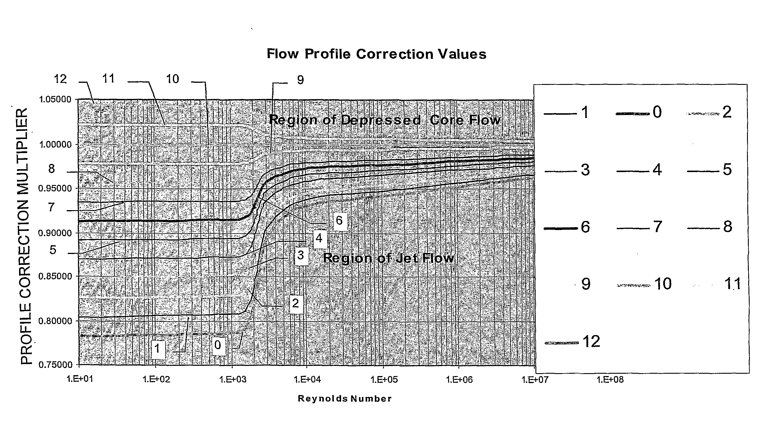
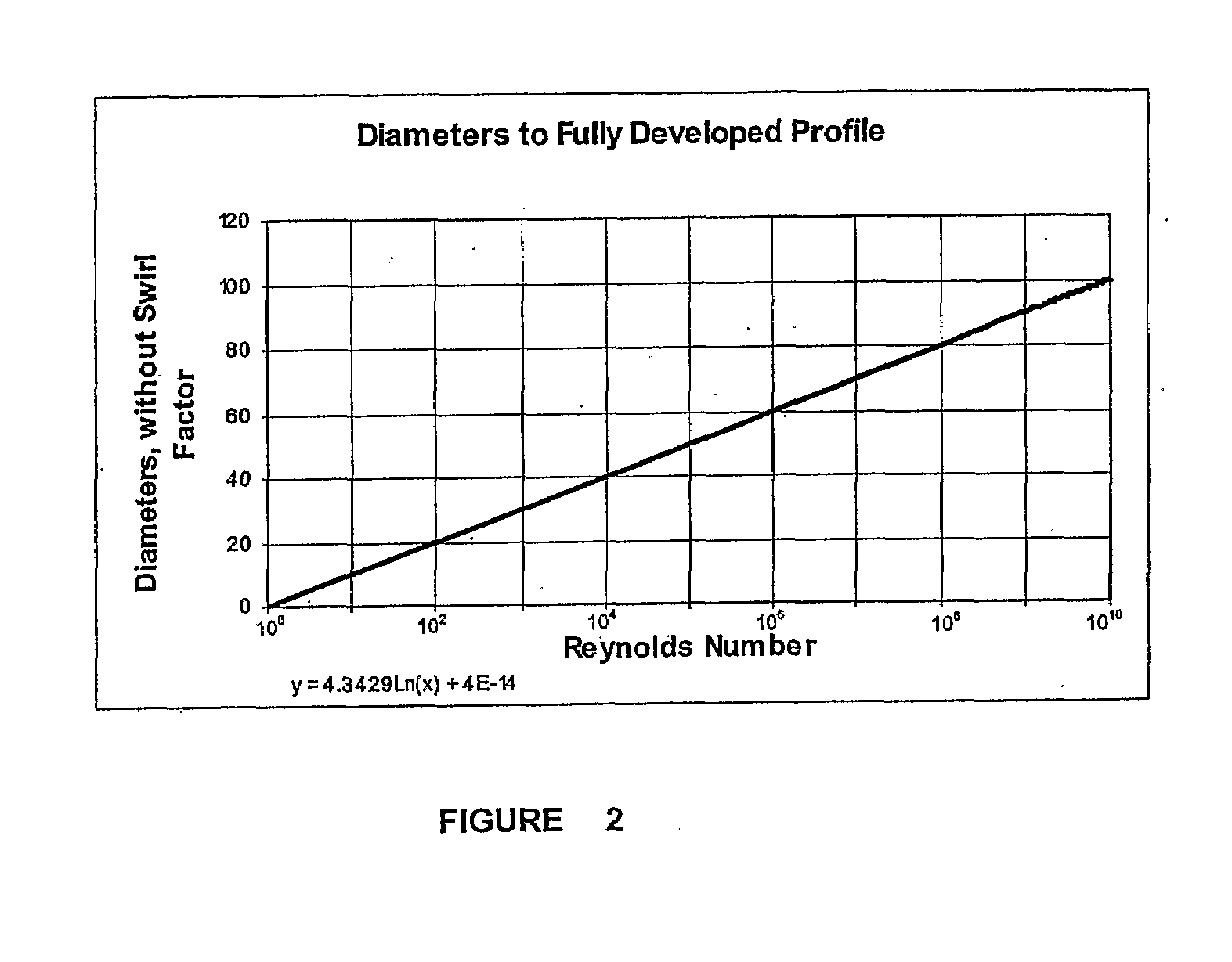
[0012]The method may further comprise dividing the number of diameters downstream from the pipe configuration where the transducer is to be installed by the number of diameters required to convert the fluid flow from the flat flow profile to the fully developed flow profile, multiplying a result of the division by ten, and subtracting a result of the multiplication from the initial curve number. If the result of the subtraction is less than or equal to 0, a fully developed flow profile correction curve may be used to determine a calibration factor. If the result of the subtraction is greater than 0, the result of the subtr

Problems solved by technology

As a result of the difference in flow rates between the area near the pipe wall and the central portion of the pipe results, an improperly calibrated flowmeter outputs inaccurate flow measurements.

Method used


Image

  • System and method for flow profile calibration correction for ultrasonic flowmeters
  • System and method for flow profile calibration correction for ultrasonic flowmeters
  • System and method for flow profile calibration correction for ultrasonic flowmeters

Examples


Embodiment Construction

[0023]Exemplary embodiments of the present invention will be described below in more detail with reference to the accompanying drawings. This invention may, however, be embodied in different forms and should not be construed as limited to the embodiments set forth herein.

[0024]The embodiments described herein may be implemented in various forms of hardware, software, firmware, special purpose processors, or a combination thereof. For example, the embodiments described herein can be implemented in software as applications comprising program instructions that are tangibly embodied on one or more program storage devices (e.g., magnetic floppy disk, RAM, CD ROM, ROM and Flash memory), and executable by any device or machine comprising a suitable architecture. Further, since the constituent system modules and method steps described herein can be implemented in software, the actual connections between the system components (or the flow of process steps) may differ depending upon the manne...


PUM


Abstract

A method for calibrating a flowmeter, comprising choosing a pipe configuration from a list of pipe configurations, defining a number of diameters downstream from the pipe configuration where a transducer is to be installed, determining an initial curve number for the chosen pipe configuration, wherein the initial curve number corresponds to a predetermined flow profile correction curve, determining a swirl factor for the chosen pipe configuration, and computing a calibration factor for a given Reynolds number.

Description

BACKGROUND OF THE INVENTION[0001]1. Technical Field[0002]The present disclosure relates to a system and method for dynamically accounting for the effect of flow profile of fluid, such as gas or liquid, on the calibration of ultrasonic flowmeters in the region between any defined pipe configuration, and the downstream location at which the flow profile becomes fully developed. Based on this system and method, an accurate calibration factor can be determined so as to assure accurate flow measurement.[0003]2. Discussion of Related Art[0004]Clamp-on ultrasonic flowmeters, which are installed on pipes to measure fluid low, have been installed without pre-calibration, without flow conditioning and in locations of convenience or where no choice of location may be made. Known methods of mounting and clamping ultrasonic flowmeters to pipes are described, for example, in U.S. Pat. No. 4,425,803 to Baumoel, entitled “Transducer Structure And Mounting Arrangement For Transducer Structure For Cl...

Claims


Application Information

Patent Timeline
IPC IPC(8): G01F25/00
CPCG01F25/0007G01F1/667G01F25/10
Inventor BAUMOEL, JOSEPH
Owner SIEMENS AG
Learn More