
Rotating shaft of louver blade for shutter assembly

a technology of rotating shaft and shutter assembly, which is applied in the direction of building components, constructions, buildings, etc., can solve the problems of unfavorable use of spare parts, and inability to directly apply the structures mentioned in p, etc., to achieve flexible deformation and easy rotation

Inactive Publication Date: 2009-03-05
NIEN MADE ENTERPRISE CO LTD
View PDF7 Cites 7 Cited by
  • Summary
  • Abstract
  • Description
  • Claims
  • Application Information

AI Technical Summary

Benefits of technology

[0015]Accordingly, the present invention is directed to a rotating shaft of louver blades for shutter assembly, in which a plurality of slots is formed at an end of a bushing, such that the bushing can be flexibly deformed. After the shaft penetrates through the bushing, the shaft bears against the external expansion force of the bushing, such that the bushing is firmly snapped within a frame, and a proper interfitting relationship is maintained between the shaft and the bushing, making the louver blade be easily rotated.
[0016]Another object of the present invention is that, the shaft penetrates through a hole of the bushing from an end of the bushing close to the louver blade, such that the shaft can still be taken out of the bushing after the bushing is combined with the frame, which is convenient for maintenance and repair process.
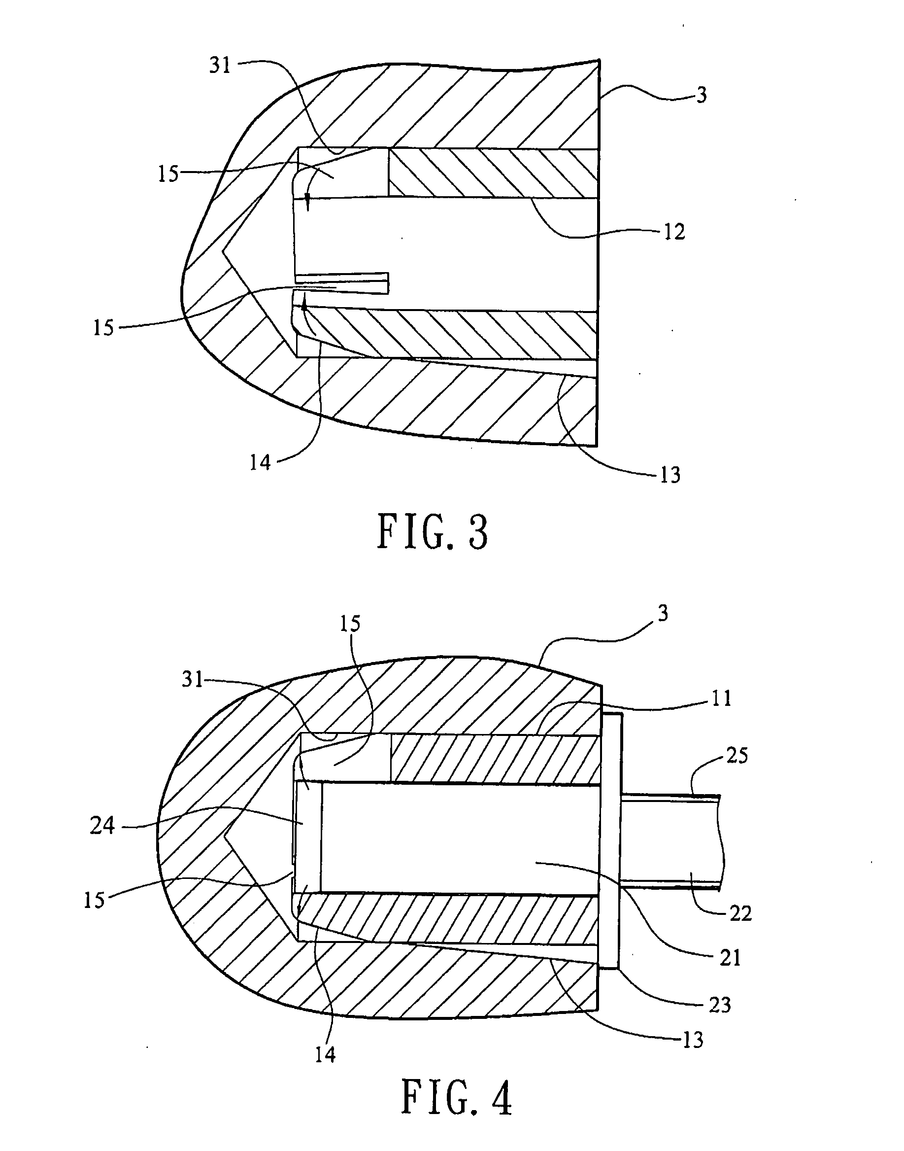
[0018]Due to the plurality of slots disposed at an end of the bushing, the bushing is capable of being deformed flexibly, and after the bushing is combined with the frame, as the fixing hole of the frame is relatively small, the end of the bushing having the slots is compressed inwards due to the flexible deformation. After the front section of the shaft penetrates through the bushing, the flexibly deformed portion is slightly expanded, such that the bushing is firmly inserted within the frame. Correspondingly, the flexibly deformed portion generates a clipping force to a part of the front section of the shaft, such that the shaft is tightly interfitted with the bushing, making the louver blade be easily rotated.

Problems solved by technology

In addition, during the disassembling process, the penetrating shaft 71 and the bushing 72 may have chance of getting damaged and need to be replaced altogether, causing unexpected wastes and excessive cost on spare part purchase
The corresponding relations among the stud shaft, the bushing, and the fixing hole of the frame in this structure are similar to that in the P.R.China Published Patent No. 2,525,224Y entitled “Louver blade positioning structure for shutter assembly”, that is to say, if the aperture of the fixing hole is too small, it is difficult for the louver blade to be assembled and rotated, and if the aperture of the fixing hole is relatively large, the loose problem tends to occur for the bushing.
However, such a structure is formed by the collar 935 and two straight flanges 921, and thus cannot be directly applied to the structures mentioned in P.R.China Published Patent No. 2,525,224Y and U.S. Pat. No. 6,655,091 to solve the problem of rotating the louver blade.

Method used


Image

  • Rotating shaft of louver blade for shutter assembly
  • Rotating shaft of louver blade for shutter assembly
  • Rotating shaft of louver blade for shutter assembly

Examples


Embodiment Construction

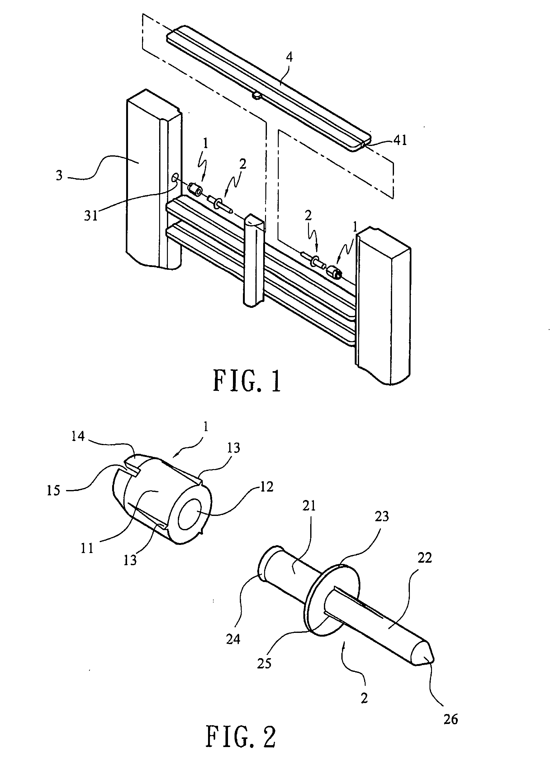
[0030]Referring to FIGS. 1 to 5, a structure of a first preferred embodiment of the present invention is shown.

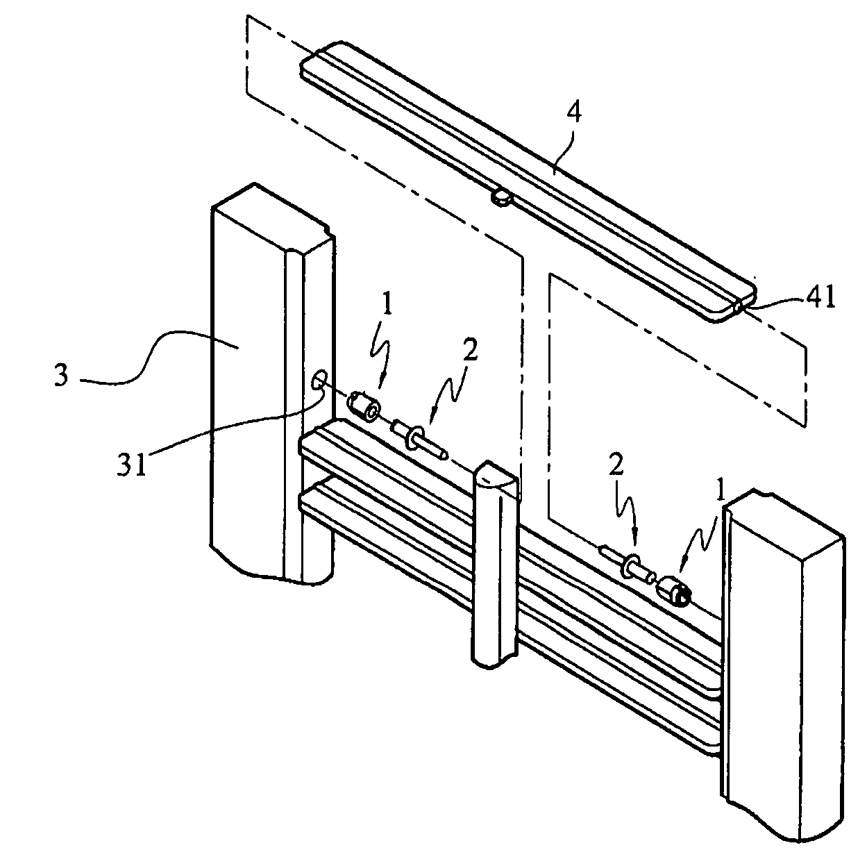
[0031]As shown in FIGS. 1 and 2, the rotating shaft of the present invention is connected between a frame 3 and a louver blade 4, and the rotating shaft includes a bushing 1 and a shaft 2. The bushing 1 is utilized to insert into a fixing hole 31 of the frame 3, and the shaft 2 is utilized to combine with the bushing 1 and a corresponding fixing hole 41 of the louver blade 4.

[0032]The bushing 1 has a body 11, and a hole 12 penetrating through the body 11. The body 11 is of cylindrical-shaped, and a plurality of lugs 13 spaced apart in equidistance intervals is protruded from an exterior surface of the body 11.

[0033]A clipping portion 14 is disposed at an end of the body 11, and has a guide angle at an outer edge thereof, such that the end away from the body 11 has a smaller outer diameter than the diameter of the body 11 of the bushing 1. The clipping portion 14 has a plura...


PUM


Abstract

A rotating shaft of louver blades for shutter assembly interconnected between a louver blade and a frame is provided, which includes a bushing and a shaft. A body of the bushing has a through hole and a plurality of slots, such that the body can be deformed flexibly. A front section of the shaft is fitted with the through hole. After the bushing is combined with the frame, the fixing hole is relatively small, which forces the end of the bushing having the slots to be compressed inwards, and after the front section passes through the bushing, the flexibly-deformed portion is expanded outwards, such that the bushing can be engaged with the frame. Moreover, the flexibly-deformed portion of the bushing generates a clipping force to the front section, such that the shaft and bushing are tightly fitted with each other, thereby making the louver blade be easily rotated and positioned.

Description

BACKGROUND OF THE INVENTION[0001]1. Field of the Invention[0002]The present invention relates to a technical field of a pivoting structure of louver blades for a shutter assembly, and more particularly to a rotating shaft of a shutter assembly, capable of making the bushing be firmly snapped within a frame, such that the louver blades can be easily rotated and positioned.[0003]2. Related Art[0004]Generally, in a shutter assembly or a louver, a rotating shaft is pivoted therebetween each louver blade and a frame, such that the louver blade can be pivotally rotated with respect to the frame, so as to readily change the angle of the slats opening from closed position.[0005]For example, in P.R.China Published Patent No. 2,525,224Y, entitled “Louver blade positioning structure for shutter assembly”, a technique is disclosed as shown in FIG. 6, in which the positioning structure includes a penetrating shaft 71 and a bushing 72. The bushing 72 is formed of a frame 721 and a shaft barrel 72...

Claims


Application Information

Patent Timeline
Patent Type & Authority Applications(United States)
IPC IPC(8): E06B7/08
CPCE06B7/08
Inventor ZHANG, DE-JUNYANG, DANIEL
Owner NIEN MADE ENTERPRISE CO LTD
Learn More