Hopper flow smoothing method and device

a technology of hopper flow and smoothing, which is applied in the direction of filtration separation, auxillary pretreatment, separation processes, etc., can solve the problems of high upward or horizontal velocity flow, inability to promote an even flow, and inability to achieve uniform flow, so as to reduce premature equipment wear and improve efficiency.

Inactive Publication Date: 2009-03-05
PORTER MCGUFFIE
View PDF15 Cites 5 Cited by
  • Summary
  • Abstract
  • Description
  • Claims
  • Application Information

AI Technical Summary

Benefits of technology

[0006]In accordance with the present invention, particulate-laden gas is directed into the hopper from one side thereof through an inlet guide. The inlet guide directs the flow against the bottom, upstream side of a porous diffuser that spans the hopper below a multiplicity of filter bags disposed at a higher position in the system. Passages through the diffuser are dimensioned and configure

Problems solved by technology

As a result, in conventional systems the flow is very non-uniform.
In many cases, the guide vanes are ineffective in promoting an even flow.
In the case of bag house filter systems, this uneven flow distribution results in regions of high up

Method used


Image

  • Hopper flow smoothing method and device
  • Hopper flow smoothing method and device
  • Hopper flow smoothing method and device

Examples


Embodiment Construction

[0022]The present invention is susceptible of embodiment in many different forms. While the drawings illustrate and the specification describes certain preferred embodiments of the invention, it is to be understood that such disclosure is by way of example only. There is no intent to limit the principles of the present invention to the particular disclosed embodiments.

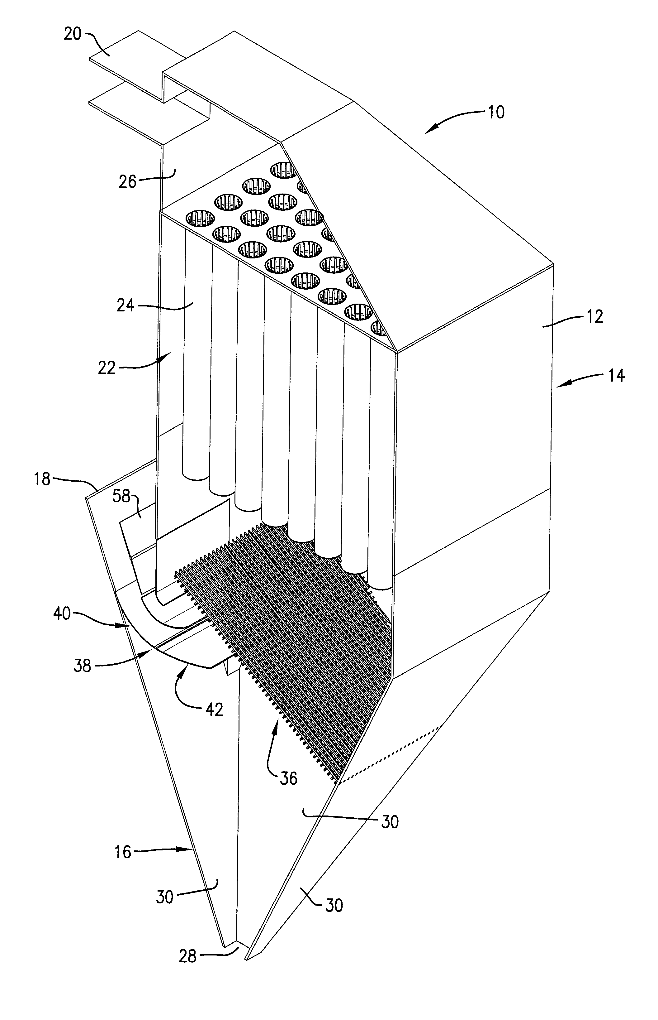
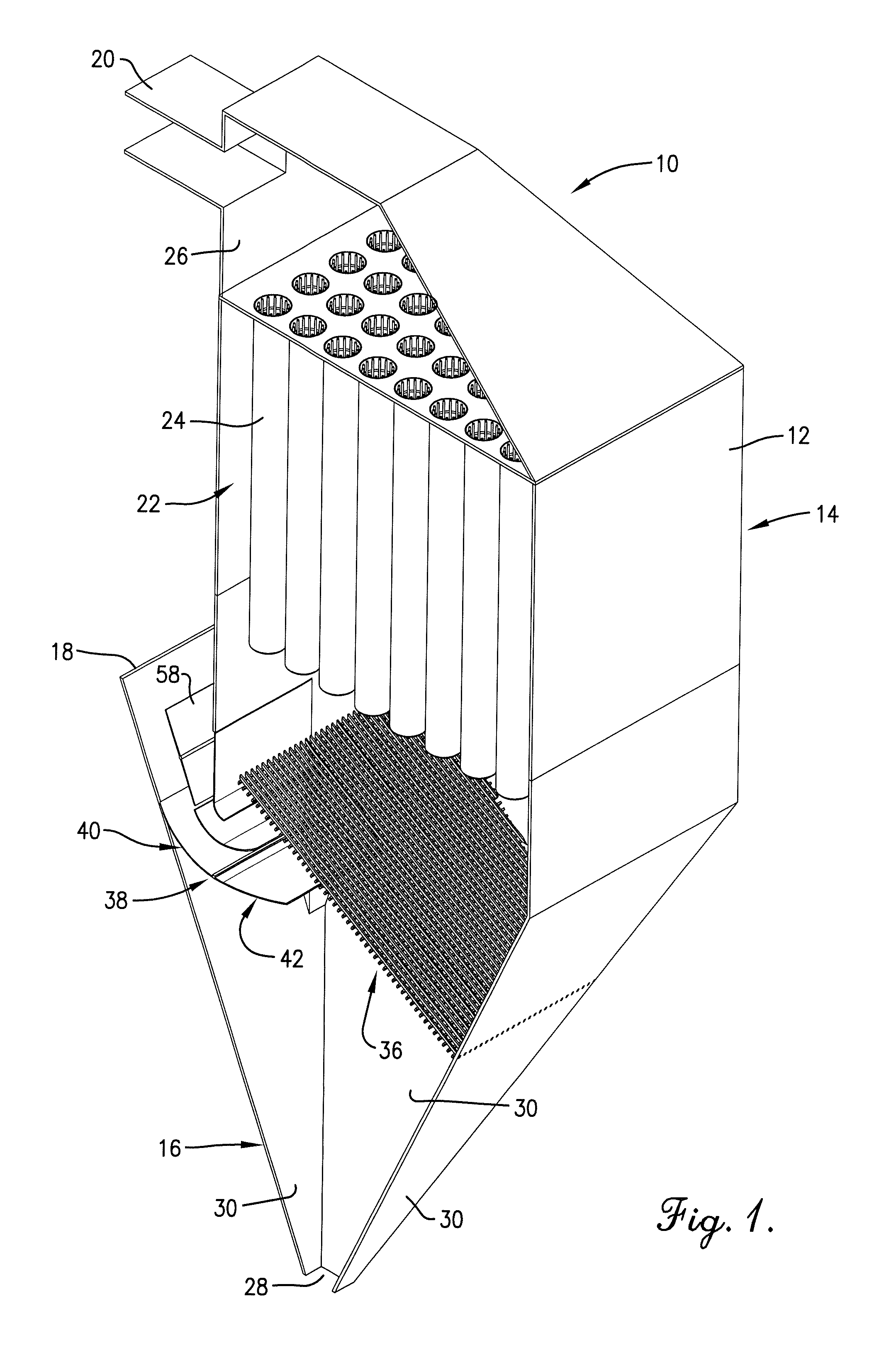
[0023]The filtration apparatus 10 broadly includes a housing 12 configured and arranged to present a bag house 14 above a hopper 16. Housing 12 has an inlet 18 through which particulate-laden gas may enter apparatus 10 and an outlet 20 through which the filtered gas may leave apparatus 10. An upper chamber 22 of housing 12 contains a multiplicity of elongated, vertically oriented, horizontally spaced fabric filter bags 24 of generally cylindrical configuration in accordance with well-known principles. Bags 24 are engaged by the particulate-laden gas as it moves upwardly through housing 12 from inlet 18 to outlet 20 to ...


PUM

PropertyMeasurementUnit
Lengthaaaaaaaaaa
Widthaaaaaaaaaa

Abstract

A filtration system for a particulate-laden stream of gas utilizes a group of fabric bags within the upper chamber of a housing as the means by which particulate matter is filtered out of the gas. The gas inlet into a lower chamber of the housing is provided with an inlet guide that directs the incoming gas against the lower side of a porous diffuser located below the group of bags and spanning at least most of the separation zone defined by the bags. Passages through the diffuser are configured to present an array of nozzles so that the gas is subjected to a pressure drop across the diffuser before flowing to the bags. The nozzle effect causes the particulate-laden gas to spread out evenly on the lower, upstream side of the diffuser and pass through the diffuser at substantially equal velocity at all passages, thereby smoothing the flow and distributing it evenly to all bags.

Description

RELATED APPLICATION[0001]This application is related to and claims the priority benefit of prior co-pending U.S. Provisional Application No. 60 / 966,441, filed Aug. 28, 2007, said Provisional Application being hereby incorporated by reference into the present specification.TECHNICAL FIELD[0002]The present invention relates to filtration systems for particulate-laden gas streams and, more particularly, to an apparatus and method for more evenly distributing particulate-laden gas to filter bags in such a system to improve the efficiency and operating life of the system.BACKGROUND AND SUMMARY[0003]An even flow of the gas phase fluid in hoppers is often desirable for the efficient operation of equipment such as bag house filter systems. Conventionally, controlling the flow is based primarily on the use of scale models and experience. As a result, in conventional systems the flow is very non-uniform.[0004]Typically, the hoppers are fed from a central header. The flow enters the hopper fro...

Claims


Application Information

Patent Timeline
IPC IPC(8): B01D46/00
CPCB01D46/02B01D46/0045
Inventor PORTER, MICHAEL A.MCGUFFIE, SEAN M.
Owner PORTER MCGUFFIE
Why Eureka
Try Eureka