

Induction cooking appliance and a method for checking the cooking capabilities of a piece of cookware
- Summary
- Abstract
- Description
- Claims
- Application Information
AI Technical Summary
Benefits of technology
Problems solved by technology
Method used
Image

Examples
first embodiment
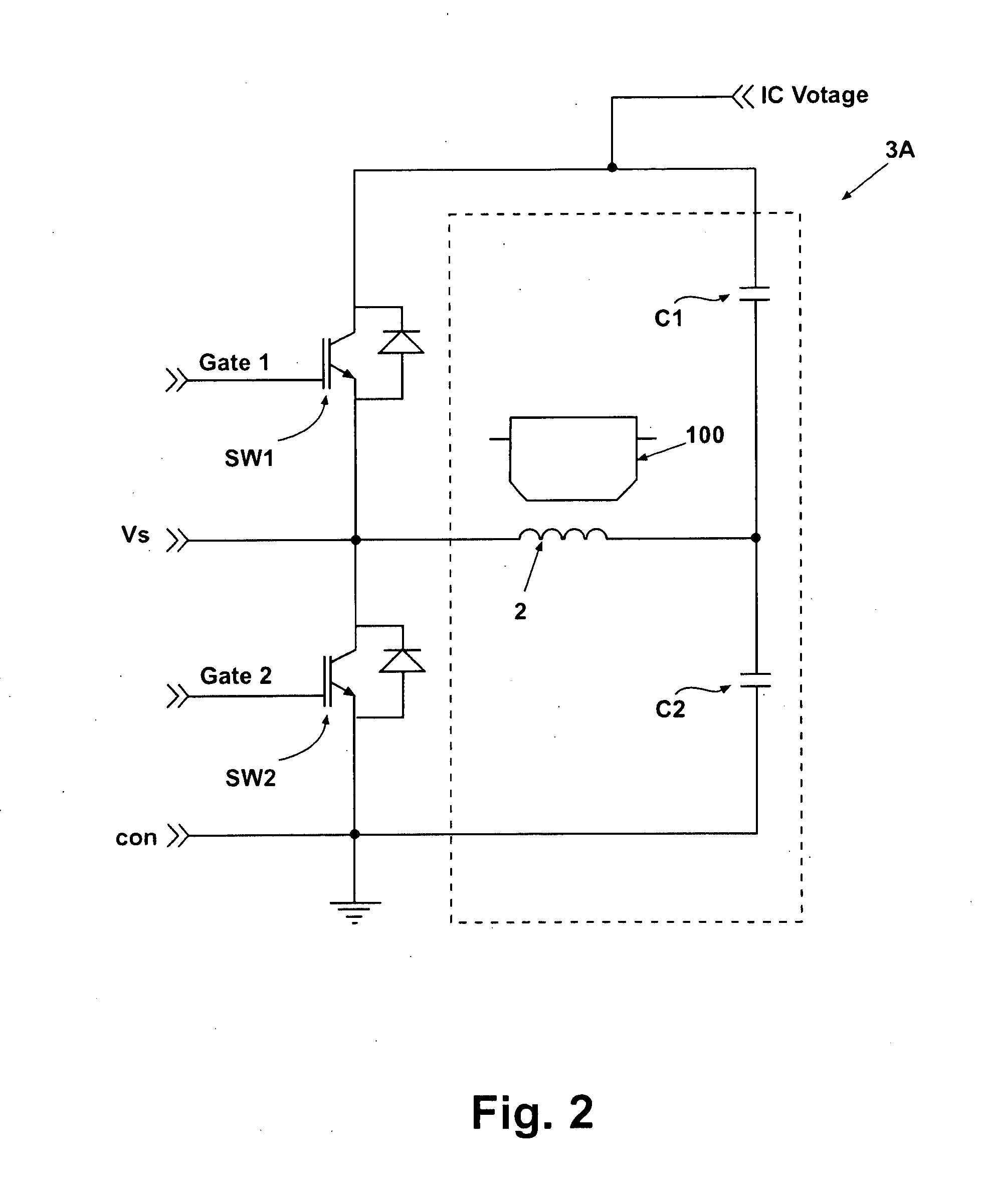
[0034]According to the present invention, a resonant Half-Bridge (HB) converter 3A is formed, the topology of which is schematically shown in FIG. 2. The converter resonant circuit 31A consists of the inductor coil 2 and the capacitors C1-C2 and it is continuously driven by the switches SW1-SW2, thus alternating the current flow direction through the inductor coil 2. The resulting AC current in the inductor coil 2 provides the required time-varying electromagnetic field. The power transfer characteristic is a function of the AC current frequency and of switching duty-cycle and it resembles the shape typical for slightly damped harmonic oscillators. Damping of oscillations is present provided by the portion of resistance of the piece of cookware 100, which is mirrored at the primary winding of the transformer modeling the inductive coupling between the inductor coil 2 and the piece of cookware 100.
second embodiment
[0035]According to the present invention, a resonant Quasi-Resonant (QR) converter 3B is formed, the topology of which is schematically shown in FIG. 3.
[0036]In this case, the resonant circuit 31B comprises the inductor coil 2 and the capacitor C3. The switch SW3 forces a current into the resonant circuit 31B only for a portion (the non-resonant one) of the oscillation time. During the remaining time (when the switch SW3 is OFF) the resonant circuit 31B can freely oscillate as a damped harmonic oscillator. The power supplied to the inductor coil 2 is therefore selected by setting the TON time, during which the switch SW3 is ON and the inductor coil 2 is charged. The time taken by the resonant circuit 31B to perform an oscillation before the switch SW3 is ON again is called TOFF. The operating frequency of the converter 3B is therefore given by fQR=1 / (TON+TOFF). It is worth to notice that the power transfer characteristic is in a direct relationship to TON and to the actual impedance...
PUM
 Abstract
Description
Claims
Application Information