
Ultrasonically activated fuel injector needle

a fuel injector and ultrasonic technology, applied in the field of spray control, can solve the problems of increasing increasing the risk of leaking, and affecting the quality of the fuel injection, so as to reduce the size of the droplet, enhance the spray, and reduce the effect of fuel pressur

Inactive Publication Date: 2009-03-05
ADVANCED PROPULSION TECH
View PDF12 Cites 9 Cited by
  • Summary
  • Abstract
  • Description
  • Claims
  • Application Information

AI Technical Summary

Benefits of technology

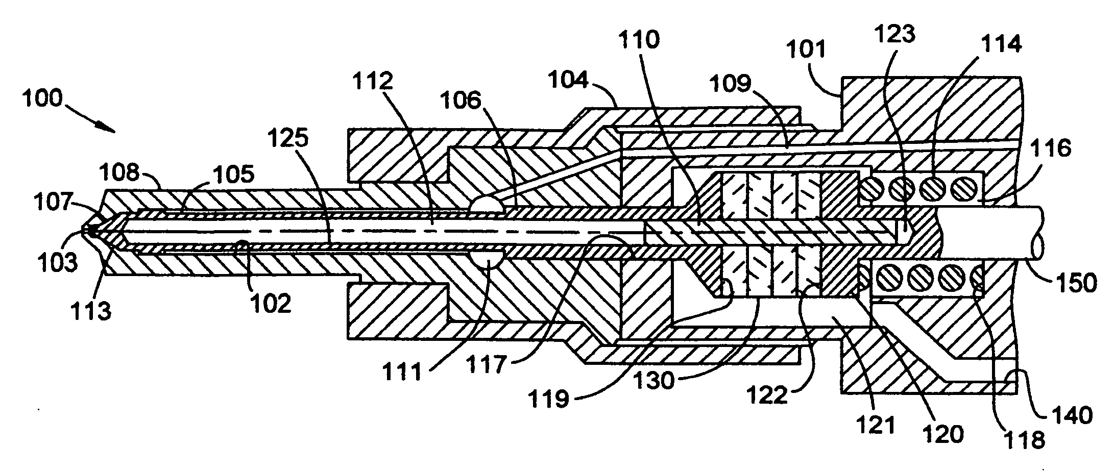
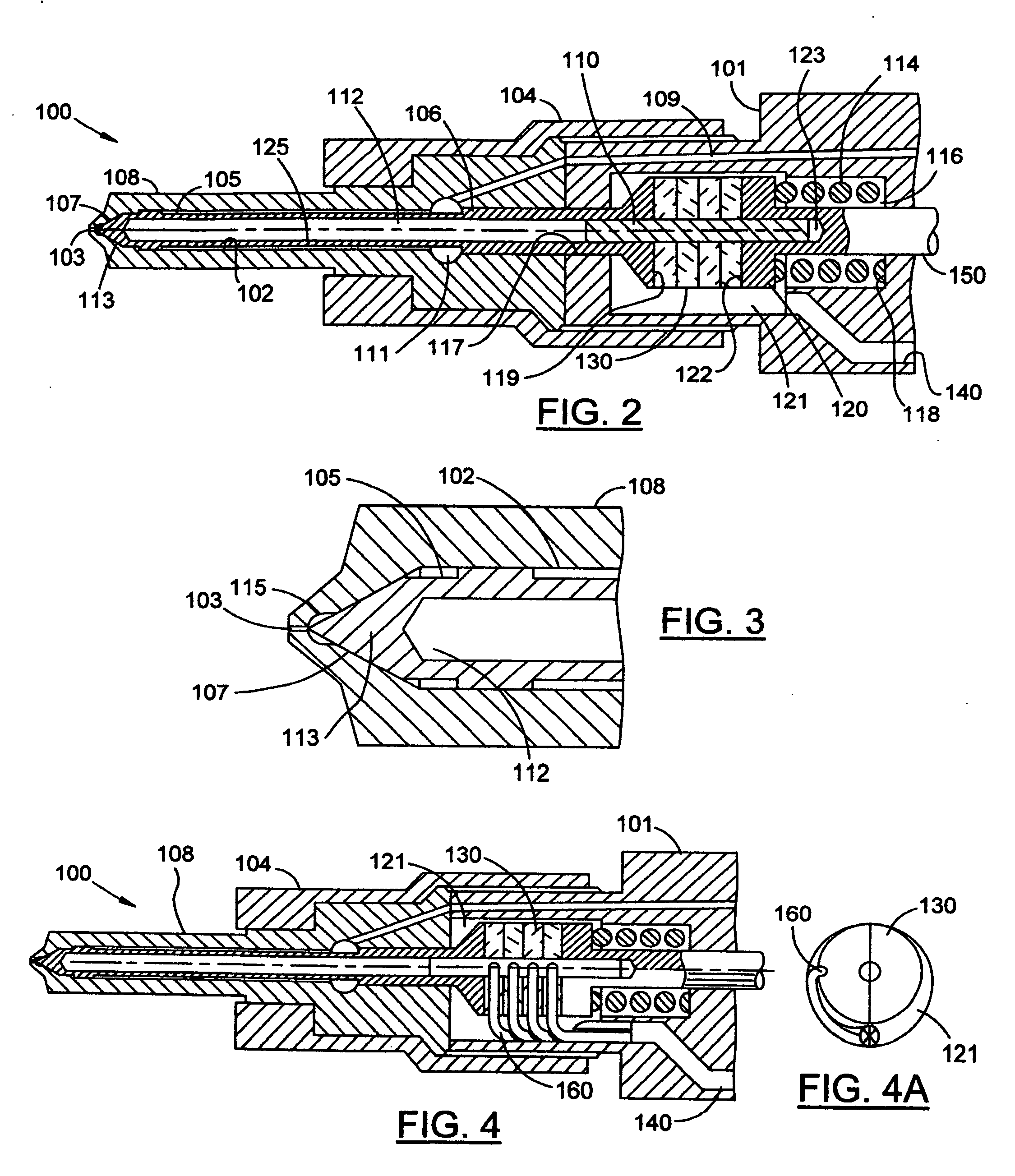
[0010]Because the fuel is driven at the nozzle orifices by the tip of the needle, the fuel pressure need not be increased beyond that which is necessary to drive the needle to its open position, nor is it necessary to provide exceptionally small orifices in the nozzle to achieve the desired atomized spray. The vibration of the tip at an ultrasonic frequency enhances the spray and reduces the size of the droplets to sub-micron sizes.

Problems solved by technology

In each case, the challenges to producing the desired fine spray are significant.
For example, multiple but smaller orifices present more surface area and resistance to the fuel passing through and are more susceptible to blockage by particles or coking.
Higher pump pressures also present the need for stronger connections, piping and injector springs, as well as more expensive pumping sources.

Method used


Image

  • Ultrasonically activated fuel injector needle
  • Ultrasonically activated fuel injector needle
  • Ultrasonically activated fuel injector needle

Examples


Embodiment Construction

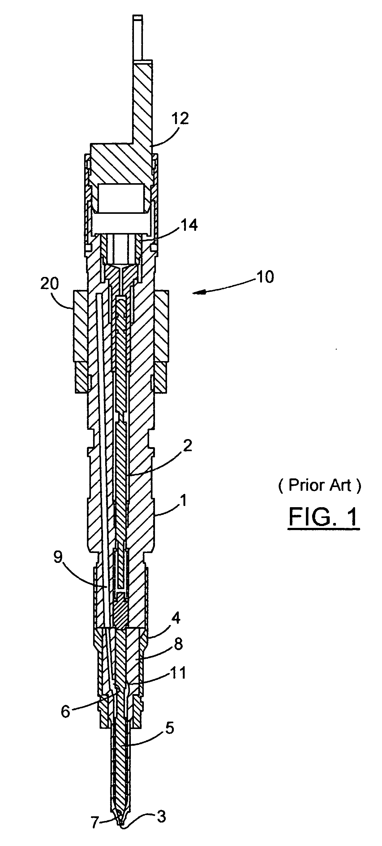
[0021]A prior art fuel injector 10 is shown in FIG. 1. The injector 10 includes an upper housing 1 which is mountable to a cylinder of an internal combustion engine. (not shown). The upper housing 1 is a cylindrically formed element that supports all the other parts of the injector. The upper housing includes a central needle bore 2 and other cavities to support a metering valve 12 at its exposed upper end and an upper needle spring 14. A fuel passage 9 is also contained in the upper housing 1 to deliver fuel under high pressure from an injector pump (not shown) to the lower end of the injector. A lower housing 4 is shown attached to the lower end of the upper housing 1. Lower housing 4 is an extension of the upper housing 1 and is used in the manufacturing assembly of the injector. Lower housing 4 supports and captures a valve housing 8 while attaching the same to the upper housing 1. Valve housing 8 defines an internal nozzle chamber 11 that is in communication with fuel passage 9...


PUM


Abstract

A fuel injector intended for use on an internal combustion engine contains an injector needle that is longitudinally driven by an ultrasonic actuator during the time the injector valve is open to provide an atomized fuel spray output of sub-micron droplet sizes. A piezoelectric disk stack is mounted within the injector housing to surround a portion of the injector needle component and is used to provide the mechanical ultrasonic stimulation to the injector valve at the end of the injector needle and set up a corresponding wave-front at the injector valve to atomize the fuel as it leaves the injector nozzle.

Description

RELATED APPLICATION[0001]This application claims the benefit of U.S. provisional application Ser. No. 60 / 966,862 filed on Aug. 28, 2007, under 35 U.S.C. 119(e).BACKGROUND[0002]1. Field of the Invention[0003]The invention is directed to the field of fuel injectors of the type employed in internal combustion engines and more specifically to the area of spray control.[0004]2. Description of the Prior Art[0005]Fuel injectors typically use needle valves and various devices to control the movement of a needle from its normally closed valve seat to an open position in order to allow pressurized fuel to be sprayed into a combustion chamber of an internal combustion engine.[0006]A major goal in the development of fuel injectors is to obtain a fine or atomized spray of fuel vapor into the combustion chamber. The smaller the droplets the more surface area is provided for mixing with air in the combustion chamber. The greater the mixture, the more even and thorough is the subsequent combustion....

Claims


Application Information

Patent Timeline
IPC IPC(8): B05B1/08
CPCF02M69/041F02M51/0603
Inventor HOFBAUER, PETERTUSINEAN, ADRIAN NICOLAIE
Owner ADVANCED PROPULSION TECH
Learn More